
Engineering selection guide · Free calculator
Optical Encoder Fit Checker: 10k Resolution and Speed
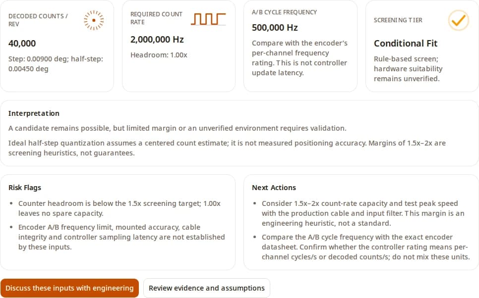
Sizing a 10k optical encoder or specifying a 10mm optical encoder shaft? First confirm whether 10k means cycles or decoded counts per revolution. At 10,000 cycles/rev and 3,000 RPM, x4 decoding needs 2 Mcounts/s; a 2 Mcount/s controller leaves no spare capacity. Use the checker to screen that electrical budget, then verify encoder frequency, mechanical shaft loads, and mounted accuracy separately.
Published · Reviewed by Frameless Servo. Review cycle: 6 months or a cited specification change.
Optical Encoder Fit Checker
Check angular resolution and counter demand before choosing hardware. Enter cycles per revolution before decoding; single-ended and differential A/B signals use the same x1/x2/x4 math.
Advisory boundary: this checker is for pre-RFQ screening. It does not replace mounted accuracy, EMC, contamination, and control-loop validation.
10k optical encoder: confirm the resolution unit
An optical encoder reads a patterned disc or scale with a light source and detector. For incremental rotary feedback, A and B channels encode movement and direction; the controller determines how many signal transitions it counts.
- 10,000 cycles/rev with x4: 40,000 decoded counts/rev and 360 / 40,000 = 0.009° per count.
- 10,000 decoded counts/rev: 0.036° per count. At x4 this corresponds to 2,500 cycles/rev, which is the value to enter in the checker.
- CPR and PPR labels: definitions vary by supplier. Record the datasheet wording and the controller mode together.
Single-ended versus differential A/B output does not set the decoding multiplier. For electrical integration and 1,000-line examples, see the optical rotary encoder wiring and timing guide.
10k resolution and speed: four worked checks
These calculations use x4 decoding and a controller rated for 2 Mcounts/s. Headroom is capacity divided by demand. They are reproducible sizing examples, not measured accuracy, customer results or product approvals.
| Rating basis / speed | A/B cycle frequency | Decoded rate / headroom | Resolution / decision |
|---|---|---|---|
| 10,000 cycles/rev · 600 RPM | 100 kHz | 0.4 Mcounts/s · 5.00× | 0.009°; count budget passes; hardware and mounted accuracy remain unverified. |
| 10,000 cycles/rev · 3,000 RPM | 500 kHz | 2 Mcounts/s · 1.00× | 0.009°; no spare counter capacity. Consider 3–4 Mcounts/s. |
| 10,000 decoded counts/rev · 3,000 RPM | 125 kHz (2,500 cycles/rev) | 0.5 Mcounts/s · 4.00× | 0.036°; coarser resolution may prevent the required tolerance. |
| 10,000 cycles/rev · 6,000 RPM | 1 MHz | 4 Mcounts/s · 0.50× | 0.009°; exceeds this counter and the cited E3 frequency limit. |
The US Digital E3 specification lists a 720 kHz A/B limit for its 10,000-cycle variant. That implies 720,000 × 60 / 10,000 = 4,320 RPM. A faster counter cannot extend that encoder limit. Other models require their own frequency and mechanical checks.
Methodology: separate cycles, counts and accuracy
- A/B cycle frequency (Hz) = cycles/rev × RPM / 60. Compare it with the encoder’s response frequency.
- Decoded count demand (counts/s) = A/B frequency × decoding multiplier (1, 2 or 4). Compare it with controller throughput in that mode.
- Angular step (degrees) = 360 / (cycles/rev × multiplier). Ideal half-step quantization assumes a centered position estimate.
- Counter headroom = rated decoded capacity / count demand. Below 1× cannot meet demand; 1× leaves no reserve. Our 1.5×–2× screening target is a heuristic, not a standard or safety factor.
At 3,000 RPM the 10k example needs 2 Mcounts/s, so a 1.5×–2× allowance means 3–4 Mcounts/s. Check pulse widths and input filters as well: a channel-frequency rating is not interchangeable with a decoded-count rating. The inverse of maximum count throughput is not controller update latency.
The checker marks an impossible ideal quantization or counter budget as Not Recommended. A narrow margin, tolerance within one count step, or unverified exposure yields Conditional Fit. Screening Pass means only that the entered arithmetic passes; encoder bandwidth and mounted accuracy remain unresolved.
Request review of a datasheet and count budgetWhy 0.009° resolution does not prove accuracy
Forty thousand counts describe the digital step size. Scale graduation, interpolation, disc eccentricity, bearing runout, coupling and temperature contribute separate errors. Follow the selected encoder’s mounting instructions; a generic rigid coupling is not a universal cure.
Build an error budget for the assembled axis, then measure it over a full revolution, both directions and the required temperature range. Distinguish absolute positioning error from repeatability. The Renishaw rotary-encoder accuracy paper explains why installation can dominate a fine resolution specification.
A clean metrology or positioning enclosure is a reasonable candidate for optical feedback. For dust, oil mist, coolant or washdown, ask for the exact package rating and exposure evidence; compare sealed optical, magnetic and resolver options under the same conditions. Technology alone does not establish environmental suitability.
Mechanical boundaries: 10mm optical encoder shaft loads
While "10k" defines the electrical counting budget, a 10mm optical encoder specifies the mechanical fit. A 10mm shaft (solid or hollow) is a common standard for mid-to-large industrial automation motors, separating the coupling requirements from the resolution.
The bearing life of a 10mm shaft encoder depends strictly on alignment and load limits, not just the shaft diameter. Manufacturers define this using L10 statistical fatigue life. For example, the SICK DFS60 series rates its 10mm bearings for 3.6 × 10¹⁰ revolutions, but only if loads remain strictly under 80 N radial and 40 N axial force. Because L10 life follows a cubic formula (L10 ∝ (C/P)³), operating right at those limit boundaries drastically reduces bearing longevity compared to nominal alignment.
To prevent premature failure, solid shafts require a flexible coupling. A typical 10mm bellows coupling tolerates ±0.3 mm radial and ±2° angular misalignment. However, combining maximum angular and radial errors simultaneously will fatigue the bellows and transmit destructive loads to the encoder bearings. Rigid couplings should never be used unless perfect concentricity is guaranteed.
Hollow-shaft 10mm models avoid coupling wind-up but introduce runout constraints. Instead of load forces, they specify permissible dynamic shaft movement (e.g., ±0.1 mm radial for the SICK DFS60). Verify your motor's axial play and radial runout before specifying a hollow shaft, as excess vibration directly degrades the mounted accuracy of your 10k resolution.
Incremental A/B versus absolute interface timing
For A/B feedback, verify voltage levels, driver/receiver compatibility, cable routing, termination, counter mode and filter settings. At the high frequencies produced by a 10k optical encoder (e.g., 500 kHz to 1 MHz), RS-422 cable length limits drop significantly. The theoretical 1,200-meter RS-422 limit applies only to low data rates. At 1 MHz, cable capacitance rounds off the square-wave edges, limiting reliable transmission to less than 50 meters and strictly requiring 120 Ω termination resistors at the receiver to prevent reflections.
SSI and BiSS transmit position words instead of exposing the same incremental counting problem. Their update budget includes serial frame length, clock frequency, processing time, cable delay and master polling. This calculator does not model those interfaces. Use the absolute encoder selection guide if startup position or protocol compatibility is the main requirement.
For a 042 optical encoder or another abbreviated listing, request the full part number first. Neither a short code nor a 10k label proves pinout, mechanical interchangeability or approval for a safety function.
Evidence to collect before approving a 10k encoder
- Identity: full part number, drawing, voltage, pinout, output type and vendor cycle/count definition.
- Rate: encoder frequency limit, controller limit in the selected decoding mode, minimum pulse widths, peak RPM and production filter settings.
- Mounting: shaft/bore dimensions, runout limits, alignment method and thermal conditions; request the installed accuracy evidence.
- Environment: enclosure and connector ratings plus compatibility with the actual dust, coolant or oil exposure.
- Acceptance: compare counts with a reference at peak speed, measure axis positioning and repeatability, and document homing and power-cycle behavior.
Record missing evidence as unresolved. ISO 230-7 offers a rotary-axis geometry test framework for machine tools; it does not certify a standalone encoder. A software screening result cannot replace that acceptance work.
Sources and limits of this review
Reviewed on 2026-09-25. Manufacturer specifications support the stated product example; formulas and software screenshots show our reproducible screening method. We have no mounted test dataset for your axis and make no claim of customer validation.
US Digital E3 product specifications
The 10,000-cycle variant has a 720 kHz A/B ceiling. The standard output is single-ended; differential accessories require separate checks.
These limits describe E3 variants, not every optical encoder.
OMRON rotary encoder technical guide
Relates resolution and shaft speed to response frequency.
Use the exact encoder and controller pulse-width specifications for final sizing.
Renishaw: The accuracy of rotary encoders
Explains the contributions of installation, eccentricity, scale and interpolation errors.
A resolution number cannot establish installed positioning accuracy.
ISO 230-7:2015 — geometric accuracy of axes of rotation
Defines the scope of geometric testing for machine-tool rotary axes.
This is an axis test reference, not certification of an encoder. Only the public scope was reviewed.
IEC 60529 — enclosure protection
Defines protection against access, solid foreign objects and water ingress.
An IP code alone does not establish coolant or oil compatibility. Only the public scope was reviewed.
SICK DFS60 incremental encoder specifications
Specifies 80 N radial and 40 N axial load limits for its 10mm solid shaft variants, and ±0.1 mm dynamic radial movement for hollow shafts.
Mechanical limits vary by mounting flange and bearing design.
Omron E6C2 rotary encoder specifications
Specifies 50 N radial and 30 N axial load limits for its 10mm shaft.
Rigid coupling can easily exceed these limits if the motor shaft is misaligned.
TIA/EIA RS-422 standard application limits
The 1,200-meter maximum length applies only at low data rates. At 500 kHz to 1 MHz typical for 10k encoders, cable capacitance limits reliable transmission to less than 50 meters, requiring 120 Ω termination.
Specific cable capacitance and receiver sensitivity will determine the exact drop-off point.
Bearing L10 fatigue life calculation (ISO 281)
Defines the L10 cubic relationship: life in revolutions is proportional to (C/P)³. Operating at maximum rated limits sharply reduces service life compared to nominal loads.
L10 is a statistical fatigue life; it does not account for seal failure, ingress, or extreme vibration.
Optical encoder selection FAQ
What does 10k optical encoder mean?
It can mean 10,000 signal cycles or 10,000 decoded counts per revolution. Vendors use CPR and PPR differently. At x4, 10,000 cycles become 40,000 counts with a 0.009° step; 10,000 decoded counts have a 0.036° step. Read the manufacturer’s definition before choosing an input.
What is a 10mm optical encoder?
It refers to an encoder with a 10mm input shaft (solid or hollow), a common mechanical standard for industrial motors. The 10mm dimension dictates the physical coupling and bearing loads, completely independent of the electrical resolution (such as 10k or 1,000 CPR).
How fast can a 10k optical encoder run?
At 10,000 cycles/rev and 3,000 RPM, each A/B channel runs at 500 kHz and x4 decoding needs 2 Mcounts/s. A 1 Mcount/s counter is insufficient. Check the encoder frequency ceiling independently: the cited E3 variant reaches 720 kHz at 4,320 RPM. Other models have different electrical and mechanical limits.
Does differential output change the x4 calculation?
No. Differential A/B transmission changes electrical signaling and noise rejection, not the decoding multiplier. Match driver and receiver levels, termination, cable length and pulse-width specifications before relying on the count-rate budget.
Does 0.009° resolution mean 0.009° accuracy?
No. Resolution is the count increment. Mounted accuracy also depends on scale error, eccentricity, interpolation, coupling, bearings and temperature. Ideal half-step quantization assumes a centered estimate; it is not a measured hardware error bound.
What does the checker’s Conditional Fit result mean?
The entered count-rate margin is below 1.5×, the tolerance is within one count step, or the environment needs validation. The 1.5×–2× margin is our screening heuristic, not a manufacturer rating or safety factor. Even Screening Pass requires exact-part and mounted validation.
Can this checker size an SSI or BiSS optical encoder?
No. It screens incremental A/B counting at x1, x2 or x4. Absolute serial feedback requires a frame-time budget covering word length, clock rate, processing time, cable delay and controller polling. Confirm those values for the selected encoder and master.
Does a 042 optical encoder label identify a compatible replacement?
No. That token alone does not establish a manufacturer, resolution or output. Obtain the full part number, supply voltage, pinout, shaft or bore dimensions, mounting drawing and output definition before evaluating a replacement.
How far can I run a 10k optical encoder cable?
At the high pulse rates of a 10k encoder (often 500 kHz to 1 MHz), standard RS-422 distance limits do not apply. Cable capacitance degrades the signal edges, typically limiting reliable transmission to less than 50 meters. You must also install a 120 Ω termination resistor at the receiver.
How long will a 10mm optical encoder bearing last?
Bearing life is calculated using the L10 fatigue formula, where life is proportional to the inverse cube of the load (L₁₀ ∝ (C/P)³). A 10mm shaft encoder might be rated for 3.6 × 10¹⁰ revolutions at its maximum load (e.g., 80 N radial). Running it at half that load yields eight times the life; exceeding the limit via a rigid, misaligned coupling will cause rapid failure.
What should I send for an engineering review?
Send the full part number and datasheet, the cycle or count definition, decoding mode, peak RPM, target tolerance, controller input rating, cable length, mounting drawing and exposure conditions. Identify missing evidence explicitly; a listing title is insufficient for approval.
Bring the evidence to an engineering review
Send the encoder and controller datasheets, your peak speed, tolerance and mounting conditions. Include the cycle/count definition and any missing evidence so the review can identify the next measurement or supplier question.