
Calculator & guide · Reviewed 2026-11-08
Magnetic Encoder: 12 CPR & 120 PPR FOC Sizing
Compare 12 CPR and 120 PPR with 12-bit feedback. Check counts, gearing, and FOC limits.
Use the fit checker ↓Encoder Fit Checker
Check motor-side counts, gearing, and drive limits.
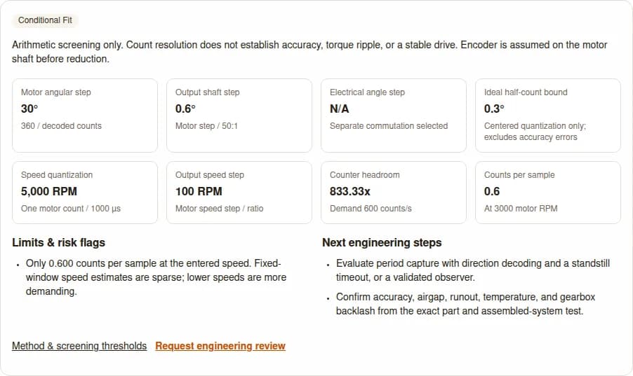
Arithmetic screening only. Count resolution does not establish accuracy, torque ripple, or a stable drive. Encoder is assumed on the motor shaft before reduction.
- Motor angular step
- 30°
- 360 / decoded counts
- Output shaft step
- 0.6°
- Motor step / 50:1
- Electrical angle step
- N/A
- Separate commutation selected
- Ideal half-count bound
- 0.3°
- Centered quantization only; excludes accuracy errors
- Speed quantization
- 5,000 RPM
- One motor count / 1000 µs
- Output speed step
- 100 RPM
- Motor speed step / ratio
- Counter headroom
- 833.33x
- Demand 600 counts/s
- Counts per sample
- 0.6
- At 3000 motor RPM
Limits & risk flags
- Only 0.600 counts per sample at the entered speed. Fixed-window speed estimates are sparse; lower speeds are more demanding.
Next engineering steps
- Evaluate period capture with direction decoding and a standstill timeout, or a validated observer.
- Confirm accuracy, airgap, runout, temperature, and gearbox backlash from the exact part and assembled-system test.
Key decisions before choosing magnetic feedback
Count convention first
120 PPR at x4 means 480 decoded counts and a 0.75° motor step. Twelve decoded counts means 30°; a 12-bit word means 4096 codes.
Gearing helps output resolution
At exactly 50:1, 12 motor counts correspond to 600 counts per output turn. Backlash and load compliance remain outside that arithmetic.
Evidence: [Ref 1]
Keep commutation motor-side
Seven pole pairs multiply a 30° mechanical count step to 210° electrical. A gearbox does not repair coarse rotor angle feedback for FOC.
Evidence: [Ref 3]
Match the actual output
AS5047P has a 14-bit SPI position word but at most 4096 ABI steps. Compare the signal delivered to the drive, then validate physical accuracy.
Evidence: [Ref 2]
Scope: motor-shaft sensing before reduction, deterministic count arithmetic, and component selection. Formula tables below are calculated examples; quoted device specifications keep their source conditions. No customer test records or field reliability measurements are asserted.
New to feedback selection? Start with the absolute encoder overview, check incremental encoder count conventions, compare the optical encoder selection guide, or size feedback for a high torque servo motor (including 12V DC bus sizing).
12 CPR & 120 PPR vs 12-bit: normalize the count convention
Pololu explicitly counts both edges of both Hall channels for its 12 CPR kit. Other suppliers specify pulses per revolution (PPR) or cycles. MPS MA732 is a magnetic angle sensor with programmable ABZ pulses; its datasheet page 23 explicitly demonstrates 120 pulses per channel and 480 decoded edges. At 4x decoding, a 120 PPR magnetic encoder gives a 0.75° motor count step; 1x decoding gives 120 counts and a 3° step. Same Sky AMT10E offers 120 PPR too, but uses capacitive sensing: it is an alternative technology, not evidence of magnetic sensor performance.
Signal frequency also scales linearly with shaft speed: f_pulse = (PPR × RPM) / 60. At 3,000 RPM, a 120 PPR encoder generates 6.0 kHz per channel (24.0 kHz decoded edge rate at 4x). At 12,000 RPM, it generates 24.0 kHz per channel (96.0 kHz edge rate). A 5,000 PPR quadrature output would demand 1.0 MHz decoded counts at 3,000 RPM. Lower count demand alone does not establish noise immunity or CPU load; verify filtering, signal levels and hardware counter use. Always normalize to decoded counts per motor revolution before sizing drive inputs or checking FOC compatibility.
| Specification | Decoded counts / codes | Mechanical step | Seven-pair electrical step |
|---|---|---|---|
| 12 decoded CPR | 12 | 30° | 210° |
| 12 cycles at x4 | 48 | 7.5° | 52.5° |
| 120 PPR (1x decoded) | 120 | 3.0° | 21.0° |
| 120 PPR (4x quadrature) | 480 | 0.75° | 5.25° |
| 12-bit word | 4096 | 0.087891° | 0.615234° |
| 14-bit word | 16384 | 0.021973° | 0.153809° |
| 16-bit word | 65536 | 0.005493° | 0.038452° |
FOC angle resolution: calculation and limits
Field-Oriented Control (FOC) uses rotor electrical angle to transform measured three-phase currents into orthogonal d/q coordinates. For motor-side counts C and pole pairs p, the electrical count step is 360p/C. The tool applies this check whenever this encoder supplies FOC angle, including geared brushless motors. For instance, a 120 PPR encoder (480 counts at 4x) on a 7-pair motor yields a 5.25° electrical step (7.5° on 10 pole pairs), exceeding the 3° screening threshold. Select separate commutation for a brushed motor or an independently validated rotor angle source.
| Quantity | Rule | Interpretation / limitation |
|---|---|---|
| Output count step | Reject when above entered maximum count step | This target is resolution; it is not ± positioning accuracy. |
| FOC electrical step | Caution >3°; reject >15° | Review drive-specific angle budget. No universal minimum bit depth. |
| Quadrature headroom | Reject <1x; caution <1.5x | Uses verified decoded count capacity; does not model pulse filtering. |
| Counts per sample | Caution <1 at entered speed | Fixed-window estimates are sparse. This is not a control stability simulation. |
For an ideal non-salient PMSM at fixed current magnitude, torque projection is proportional to cos(ε), where ε is electrical angle error. Assuming a centered quantizer only, 120 PPR at 4x and ten pole pairs gives a 7.5° electrical step and an ideal ±3.75° bound. The endpoint projection reduction is 1 − cos(3.75°), about 0.21%. This is a calculated static illustration, not measured torque ripple or a prediction of noise, heating or control stability.
With 12 decoded counts and seven pole pairs, electrical spacing is 210°. In that same ideal centered model, the ±105° endpoint exceeds 90° and torque projection can reverse sign. Actual behavior depends on rotor estimation, startup, protection and drive tuning; spacing alone does not prove runaway. The tool rejects this coarse motor-side feedback under its stated heuristic. A gearbox leaves this electrical spacing unchanged.
Evidence: [Ref 3]
Gear ratio improves output count spacing, not accuracy
A 12 CPR or 120 PPR magnetic encoder is useful for many brushed or geared actuators because commutation is handled separately (or by Hall switches) and reduction produces more motor counts per output turn. For example, a 120 PPR encoder (480 counts at 4x) paired with a 20:1 planetary gearbox yields 9,600 counts per output revolution (0.0375° or 2.25 arcmin step), while a 50:1 reduction provides 24,000 counts per output revolution (0.015° or 0.9 arcmin step).
Mechanical reduction improves output-equivalent count spacing; physical accuracy still depends on the selected gearbox’s backlash, transmission error, stiffness and load. No universal numerical range is established by the sources here. Obtain the exact model’s specifications and measure reversal hysteresis under the intended load. Motor-mounted counts cannot observe lost motion on the load shaft. An auxiliary load-side encoder can measure that motion for a validated dual-loop control strategy; it does not remove mechanical backlash or guarantee bidirectional accuracy.
| Reduction N:1 | Output-equivalent counts | Output count step | Ideal centered half-count |
|---|---|---|---|
| 1 | 12 | 30° | ±15° |
| 30 | 360 | 1° | ±0.5° |
| 50 | 600 | 0.6° | ±0.3° |
| 100 | 1200 | 0.3° | ±0.15° |
Evidence: [Ref 1]
Fixed-window velocity quantization
Counting position changes over a sample window Ts gives v = 60Δcount/(C×Ts) motor RPM. One count changes the estimate by Δv = 60/(C×Ts). Ts is in seconds. The output-shaft speed increment is Δv/N. For 120 PPR at 4x (C = 480 counts), a 1 ms window (Ts = 0.001 s) produces a quantization step of 125 RPM. At 100 µs, this step reaches 1,250 RPM. These values are estimator increments, not RMS noise power. Noise statistics depend on edge timing, sampling phase, differencing and filtering; a uniform independent quantization-noise assumption is not generally valid for sparse periodic counts.
| Decoded counts C | 50 µs | 100 µs | 1 ms | 10 ms |
|---|---|---|---|---|
| 12 | 100000 | 50000 | 5000 | 500 |
| 120 (1x) | 10000 | 5000 | 500 | 50 |
| 480 (120 PPR 4x) | 2500 | 1250 | 125 | 12.5 |
| 4096 | 292.969 | 146.484 | 14.648 | 1.465 |
| 16384 | 73.242 | 36.621 | 3.662 | 0.366 |
| 65536 | 18.311 | 9.155 | 0.916 | 0.092 |
At 50 motor RPM and 12 counts/rev, the count rate is 10/s: one edge every 100 ms on average. With 100 µs windows, that is about 999 zero-count windows then one one-count window. For 120 PPR at 4x (480 counts/rev) at 50 RPM, the count rate is 400 counts/s (one edge every 2.5 ms). In a 1 ms velocity loop, most cycles read 0 counts (0 RPM) and other cycles read 1 count (125 RPM). This can make raw feedback jump even at steady speed; evaluate period timing or filtering against the required response time and speed error.
Evidence: [Ref 4]
Period capture, hybrid estimation, and observers
| Method | Useful operating condition | Failure / uncertainty | Minimum mitigation |
|---|---|---|---|
| Fixed-window count | Many counts within each window | Sparse counts at low speed; averaging delay | Lengthen window or combine with period capture. |
| Period capture | Long enough edge interval to resolve timer ticks | No fresh edge at standstill; long updates at low speed | Direction decoding, timeout, overflow and reversal policy. |
| M/T hybrid | Wide speed range | Switching and synchronization errors | Test changeover hysteresis and timestamp consistency. |
| Model-based observer | Known plant and measured inputs | Load disturbance, model mismatch, observability limits | Validate startup, reversal, low-speed load steps, and residual error. |
A period estimate uses v = 60/(C×Δt) when the captured interval spans one decoded count. Verify which edges the capture unit measures. For C = 480 and Ts = 1 ms, 125 RPM gives one count per window; this marks sparse-count behavior, not a universal M/T switching speed. Select crossover and hysteresis from timer error and permitted update delay. Choose standstill timeout from the slowest supported speed: at 1 RPM and C = 480, an edge takes 125 ms, so a 50 ms timeout would falsely report standstill between valid edges.
A Luenberger tracking observer or Kalman filter can use x̂[k+1] = Ax̂[k] + Bu[k] + L(y[k] − Cx̂[k]); its model, gain selection, and unmeasured load determine estimation quality. Smooth output is not evidence of correct angle or zero delay.
Evidence: [Ref 4]
Hall, AMR, GMR, and TMR: compare complete sensors
The sensing material alone does not determine bit depth, accuracy, current, or immunity. Compare a specified magnet, sensing architecture, signal conditioning, calibration, and selected interface. AS5047P is a Hall example; MA732 is a separate magnetic angle IC and should not be inferred to use the same architecture. Temperature grade, current, field range, bandwidth and repeatability belong to exact part specifications. Where sensing has angle ambiguity, confirm how the complete device resolves a full turn.
| Technology | Signal mechanism / architecture | Decision check |
|---|---|---|
| Hall | Field-dependent transverse voltage; integrated arrays possible | AS5047P demonstrates 14-bit SPI with a lower-resolution ABI path. |
| AMR | Resistance depends on magnetization orientation | Check angle periodicity, field range, ambiguity resolution, and conditioning. |
| GMR / TMR | Spin-dependent resistance / tunneling in layered structures | Compare full sensor limits instead of assigning a universal accuracy ranking. |
| TAS2143 TMR example | Analog differential sin/cos; 20–80 mT applied field | ±0.15° typical at 25°C; ±0.8° over temperature; not a stray-field rating. |
Uniform-field rejection does not establish immunity to spatial field gradients near motor conductors. There is no verified universal clearance or shield specification in the cited evidence. Test the selected sensor, magnet and current routing at worst-case operating conditions; validate placement changes or shielding in that assembly.
Need a matched motor and sensor? Request a feedback integration review with the selected output, motor pole pairs and installed accuracy target.
High-speed delay and DAEC: separate static and dynamic error
Sensor acquisition, filtering and the selected interface contribute delay t. AS5047P System Characteristics lists up to 1.9 µs after DAEC at ABI/UVW, while its SPI core-read path lists 90–110 µs. These are different signal paths, not interchangeable latency values. For an assumed uncompensated delay at constant speed, latency creates mechanical angle lag of 6×RPM×t degrees (with t in seconds). Multiply by pole pairs p for electrical lag: Δθe = 6·p·RPM·t. The following table illustrates an assumed 10 µs delay across speed ranges for a 7 pole-pair motor.
| Motor RPM | Mechanical lag | Electrical lag | Compensated device error |
|---|---|---|---|
| 1000 | 0.06° | 0.42° | Not predicted by this model |
| 5000 | 0.30° | 2.10° | Check datasheet output and test conditions |
| 14500 | 0.87° | 6.09° | Check residual delay and acceleration response |
| 28000 | 1.68° | 11.76° | Speed rating does not establish accuracy |
Dynamic Angle Error Compensation (DAEC) reduces dynamic angle error in supported paths. Use the datasheet residual error and acceleration test conditions rather than treating an ideal extrapolation formula as the device transfer function. Include frame transmission, angle timestamp and drive computation in the total delay budget, and test reversals and acceleration. DAEC does not establish zero total delay.
Hollow-shaft Nonius feedback and phase margins
An off-axis ring preserves the hollow shaft bore for cabling, laser paths, or fluid delivery. Dual-track Nonius systems combine a fine master track with N pole pairs (e.g. N = 32, with an 11.25° mechanical period) and a Nonius track with N−1 pole pairs (e.g. 31 pole pairs, with an 11.6129° period). Over one complete revolution (360°), subtracting the two track phases modulo 2π produces a unique sawtooth phase difference Δφ that identifies the absolute master sector.
Incorrect sector identification can cause a whole-period position error. The ideal N/N−1 arithmetic above does not specify a real ring/readhead synchronization tolerance. The cited iC-MU and AksIM-2 overviews do not establish a universal phase margin or a guarantee that every fault is flagged before torque is enabled. Obtain exact mounting and diagnostic limits, then test controller fault response.
Installation risks: geometry, magnetic fields, and enclosure
| Risk | Why it matters | Verification / alternative |
|---|---|---|
| Eccentricity / radial error | Periodic angle error and track disagreement | Measure against ring/readhead drawing; distinguish eccentricity from TIR. |
| Airgap / axial wobble | Changes field amplitude, signal quality, or contact clearance | Use specified rideheight and diagnostics at hot/cold conditions. |
| Stator / busbar stray fields | Uniform fields and gradients can distort sensed angle | Route paired conductors away; test current extremes; validate any shield. |
| Dust, oil, magnetic debris | Enclosure and magnet contamination remain relevant | Specify assembly IP rating, seals, corrosion and particle exposure. |
| Backlash / compliance | Motor encoder cannot observe lost output motion | Measure reversal hysteresis; add load-side feedback if needed. |
For a simplified small-offset circular scale, angular eccentricity error amplitude is approximately (e/r) radians, or 57.3e/r degrees, where e is center offset (not automatically total indicated runout). For e = 0.05 mm and radius r = 15 mm, this geometric error reaches 0.191° (11.5 arcmin). This geometric example is not a measured magnetic sensor error. Airgap sensitivity depends on magnet geometry and field harmonics; automatic gain control does not restore lost signal-to-noise ratio or establish angle accuracy. Use part-specific rideheight, field range and diagnostic limits.
Temperature changes magnet field strength and sensor behavior; use the selected magnet grade and sensor temperature specifications. ISO 11452-8:2015 describes automotive immunity testing against continuous narrowband magnetic disturbance fields. Confirm the applicable test plan, orientation, frequency, current routing, and acceptance criteria.
Sin/cos calibration: what normalization can establish
Analog magnetic sensors generate quadrature voltages u1 = A1·cos(θ) + c1 and u2 = A2·sin(θ + δ) + c2. Sensor amplifier drift introduces DC offsets (c1, c2), asymmetric airgap causes channel gain mismatch (A1 ≠ A2), and sensing element placement errors cause phase non-orthogonality (δ ≠ 0). These imperfections distort ideal circular Lissajous trajectories into a tilted, shifted ellipse, producing first-harmonic (from offset) and second-harmonic (from gain and phase) angle errors.
Heydemann’s 1981 method identifies these five parameters from quadrature data and maps the distorted ellipse back to a centered unit circle: u1,corr = (u1 - c1)/A1, and u2,corr = [ (u2 - c2)/A2 - sin(δ)·u1,corr ] / cos(δ), followed by θcorr = atan2(u2,corr, u1,corr). This is an ideal signal-model derivation, not a measured magnetic encoder improvement. The cited interferometry paper does not establish a numerical residual accuracy for this assembly. Normalization cannot eliminate higher-order harmonic distortion from non-sinusoidal magnet pole magnetization, temperature-dependent drift, or gearbox backlash. Residual accuracy requires verification against an independent optical reference.
Evidence: [Ref 8]
Choose the signal path before calculating controller limits
| Interface | What the controller receives | Required check |
|---|---|---|
| A/B/Z | Incremental phase transitions plus optional index | Decode factor, total count rate, pulse width, filtering, logic/transceiver levels. |
| UVW | Commutation states tied to configured motor pole pairs | Pole count, electrical alignment, phase order, compatible drive strategy. |
| SPI | Device-specific position and status frames | Selected word resolution, parity/CRC, register path, latency, PCB signal integrity. |
| SSI | Synchronous position word | Bit length, timing, status extensions; basic SSI does not inherently guarantee CRC. |
| BiSS C | Position/status with protocol-defined CRC | Profile, CRC polynomial/length, frame rate, physical layer, controller compatibility. |
For quadrature feedback, total decoded demand is C×RPM/60 counts/s. For a 120 PPR encoder at 4x (480 counts/rev) running at 3,000 RPM, the demand is 24,000 counts/s (24 kHz edge rate); at 12,000 RPM, it is 96,000 counts/s. In x4 mode, individual channel frequency is one quarter of that demand (6 kHz and 24 kHz respectively). Compare this against a quadrature output providing 65,536 decoded counts per revolution: it would demand 13.1 MHz at 12,000 RPM. A 16-bit serial position word does not imply that quadrature count rate.
Serial feedback (SPI, SSI, BiSS C) transmits discrete digital packets rather than pulse trains. Standard SSI lacks built-in CRC error checking; single-bit transmission noise on the factory floor can corrupt position words undetected. BiSS C defines CRC protection; verify CRC length, polynomial, status bits and frame structure for the selected device profile. CRC detects covered transmission errors and does not guarantee sensor accuracy or cable performance. The tool marks quadrature headroom N/A for serial interfaces and requires verifying frame rate against loop update time.
Worked calculations: assumptions, result, and next test
These are illustrative calculations and design exercises, not customer deployments, bench measurements, or field reliability records. Each example states the information still needed before release.
1 · Brushed 12 CPR & 120 PPR gearmotor
Assumptions: C=12 decoded counts (or 120 PPR at 4x = 480 counts), exact N=50, motor speed=3000 RPM, Ts=1 ms.
Result: For 12 CPR: output step 0.6°, fixed-window motor speed increment 5000 RPM. For 120 PPR at 4x: output step 0.015° (0.9 arcmin), speed increment 125 RPM.
Next test: Assess period capture, timeout, and specified gearbox backlash; test crawl speed and reversal.
2 · Geared brushless FOC sizing
Assumptions: C=12 vs 120 PPR (480 counts at 4x), p=7, exact N=100; encoder supplies rotor angle.
Result: 12 CPR yields 210° electrical step (tool rejects >15°). 120 PPR yields 5.25° electrical step (caution >3°). 100:1 reduction yields 0.0075° output step but cannot refine commutation.
Next test: Set the drive-specific angle budget; choose finer motor feedback or validate a separate rotor estimator and startup sequence.
3 · AS5047P output choice
Assumptions: Same sensor: 14-bit absolute SPI versus maximum 4096-step ABI; p=7.
Result: SPI code step 0.021973° (0.153809° electrical); ABI step 0.087891° (0.615234° electrical).
Next test: Check datasheet accuracy, corrected angle path, startup alignment and controller timing.
4 · High-speed counter limit
Assumptions: C=16384, motor speed=12000 RPM, controller decoded capacity=2 MHz.
Result: Demand 3.2768 MHz; headroom 0.610x. If C=2048, demand is 409.6 kHz (not 682 kHz).
Next test: Confirm resolution remains adequate, or evaluate serial feedback and its complete frame timing.
5 · TMR temperature budget
Assumptions: TAS2143 source conditions: typical 25°C versus specified over-temperature angle error.
Result: ±0.15° typical at 25°C is not the ±0.8° over-temperature value.
Next test: Use the correct error budget; measure magnet, mounting and ADC contributions separately.
6 · Hollow bore with stray fields
Assumptions: Central passage required; motor/busbar current and ring geometry not yet specified.
Result: Off-axis feedback is a candidate. Accuracy, allowed airgap and immunity remain unknown.
Next test: Obtain ring/readhead drawings and test maximum-current routing before choosing a shield or sensor.
Selection tradeoffs and total installed cost
| Candidate | Reason to evaluate | Cost / mismatch risk | Practical selection action |
|---|---|---|---|
| Low-count magnetic gearmotor (12 CPR / 120 PPR) | Coarse output feedback with independent commutation | Backlash, capture-timer work and low-speed tuning may dominate savings | Confirm exact ratio, output resolution and estimator before buying. |
| Integrated magnetic angle IC | Compact sensing near a solid shaft end | Magnet, PCB, alignment, transceiver and calibration are extra | Compare actual output path and full installed error budget. |
| Off-axis magnetic ring | Bore remains open for cabling or services | Ring/readhead alignment, calibration and diagnostics add integration work | Request matched ring drawings and assembly tolerances. |
| Optical system | Candidate when a selected system meets tighter accuracy requirements | Mounting, sealing and contamination management depend on design | Compare specified products and environmental qualification. |
| Resolver | Candidate for demanding thermal or mechanical conditions | Resolver-to-digital conversion, excitation and packaging add complexity | Budget electronics, angle accuracy, bandwidth and test effort together. |
Primary sources and evidence boundaries
Published · Reviewed · Published and maintained by Frameless Servo. Review every six months, or sooner when linked datasheets, protocols or screening assumptions change. Next review: 2027-05-08. Send a source correction through our engineering contact.
Source review date: . Device limits retain their source conditions. Tables labeled “calculated” are reproducible arithmetic; local tool thresholds are screening choices. Public evidence does not establish performance for an unspecified motor/encoder assembly. Current prices, guaranteed shielding thicknesses, generic immunity limits, and unmeasured field outcomes are intentionally not asserted.
[1] Pololu: Romi 12 CPR magnetic encoder kit
Supports: Two Hall channels and a six-pole disc; 12 counts per motor revolution when both edges of both channels are counted.
Boundary: This decoding convention belongs to this product. Check other suppliers and use the exact gearbox ratio.
Read primary source ↗[2] AS5047P datasheet v2-00, 2021-07-22 (Infineon-hosted legacy ams document)
Supports: 14-bit absolute SPI position, programmable ABI up to 4096 steps / 1024 pulses, DAEC, and UVW for 1–7 pole pairs. See General Description and ABI Incremental Interface.
Boundary: Core bits do not equal ABI counts. No native BiSS-C interface. Dynamic error, field immunity, and timing depend on the specified output and test conditions.
Read primary source ↗[3] Texas Instruments SPRABQ2, July 2013: Sensored FOC of 3-Phase PMSMs
Supports: Explains rotor-oriented d/q current control and sensored implementation. See sections 4 and 5.
Boundary: Does not define a universal minimum encoder bit depth or the 3° / 15° screening thresholds used here.
Read primary source ↗[4] Texas Instruments: eQEP position and speed example
Supports: Demonstrates fixed-window and capture-period speed measurements, with 4000 decoded counts from a 1000-line quadrature signal.
Boundary: A hardware example, not a stability guarantee for a particular motor, observer, or control-loop tuning.
Read primary source ↗[5] TDK TAS2143-AAAA product specification
Supports: Analog differential sin/cos TMR sensor: ±0.15° typical at 25°C, ±0.8° over temperature, 20–80 mT operating field, −40°C to +150°C.
Boundary: The operating field is the applied sensing field, not a stray-field immunity rating. Typical room-temperature accuracy is not the full-temperature limit.
Read primary source ↗[6] iC-Haus: iC-MU off-axis absolute position encoder
Supports: Integrated Hall sensors scan master and nonius tracks; provides single-turn absolute position, serial and incremental outputs, and UVW commutation.
Boundary: Choose the exact IC, pole pitch, ring, filtering, and configuration. No universal runout or Nonius phase margin is established by this overview.
Read primary source ↗[7] RLS: AksIM-2 off-axis rotary absolute encoder
Supports: Off-axis ring encoder with self-monitoring, self-calibration options and serial interfaces; product variants offer up to 20-bit resolution.
Boundary: Use the selected ring/readhead drawing and datasheet for rideheight, temperature, accuracy, and calibration conditions.
Read primary source ↗[8] Heydemann, Applied Optics 20, 3382–3384 (1981)
Supports: Determination and correction of quadrature fringe measurement errors in interferometers; DOI 10.1364/AO.20.003382. Corrects gain mismatch, quadrature phase error, and zero offsets.
Boundary: Original work concerns interferometers. Applying the method to magnetic sin/cos signals is an engineering adaptation; no magnetic encoder residual accuracy is guaranteed.
Read primary source ↗[9] ISO 11452-8:2015, edition 2: Immunity to magnetic fields
Supports: Automotive component test method for continuous narrowband magnetic disturbance fields using radiating-loop or Helmholtz-coil arrangements.
Boundary: A test method does not establish compliance or a 50 mT immunity rating for an untested encoder. Confirm edition and test plan before qualification.
Read primary source ↗[10] BiSS Association: BiSS C Protocol Description, revision D2
Supports: Defines BiSS C serial communication including data protection with CRC.
Boundary: Basic SSI does not inherently include the same CRC protection. Cable length and clock rate require the encoder, transceiver, and controller specifications.
Read primary source ↗[11] MPS MagAlpha MA732 datasheet, revision 1.1, 2022-08-08
Supports: Magnetic angle sensor with programmable 1–1024 pulses per channel per turn. Tables 19–20 on page 23 explicitly show 120 pulses = 480 edges and PPT = 119.
Boundary: Verify the exact part, register configuration and controller decode factor. ABZ counts differ from the serial word; effective resolution depends on filtering. This is a sensor IC, not a complete housed encoder.
Read primary source ↗[12] Same Sky: AMT10E capacitive incremental encoder
Supports: The manufacturer identifies a capacitive sensing platform and 16 selectable resolutions from 120 to 5120 PPR.
Boundary: A non-magnetic alternative. Sharing a 120 PPR output does not establish the same sensing technology, environmental performance or controller compatibility.
Read primary source ↗Engineering FAQ
Counts and resolution
What does 12 CPR or 120 PPR magnetic encoder mean?
For the cited Pololu kit, 12 CPR means 12 decoded counts per motor-shaft revolution (30° step). A 120 PPR magnetic encoder supplies 120 cycles per channel; counting both edges of A and B gives 480 counts (0.75° step), while 1x decoding gives 120 counts (3° step). MPS MA732 datasheet page 23 gives an explicit 120-pulse configuration. Same Sky AMT10E also offers 120 PPR, but uses capacitive sensing. Verify both the technology and decode factor.
Is 12 CPR or 120 PPR the same as 12-bit?
No. Twelve decoded counts give a 30° step, and 120 PPR (480 counts at 4x) gives a 0.75° step. A 12-bit position word has 4096 codes and a 0.087890625° code step. Furthermore, resolution is quantizer granularity; physical accuracy requires accounting for sensor nonlinearity, runout, and thermal drift.
What if the supplier means 12 cycles per revolution?
At x4 quadrature decoding, 12 cycles become 48 counts (7.5° step). Enter 48 in the tool, not 12. Confirm whether your microcontroller or motion controller timer hardware (such as TI eQEP or STM32 timer encoder mode) counts 1x, 2x, or all four edges.
Which shaft does the count value refer to?
This tool assumes the encoder measures the motor shaft before the gearbox. Output-equivalent counts are motor counts multiplied by the exact reduction ratio. A load-side encoder needs a separate geometry model; do not use its count value here to assess motor-side FOC.
Does a nominal 50:1 gearbox always give 600 output counts?
Only if its exact reduction is 50:1 and the motor encoder gives 12 decoded counts. If using 120 PPR at 4x (480 counts), a 50:1 ratio yields 24,000 output counts (0.015° or 0.9 arcmin step). Catalog ratios are often rounded; enter the exact tooth count ratio from the manufacturer specification.
Does a 0.6° count step guarantee ±0.3° positioning?
No. A centered quantizer has an ideal half-count bound of ±0.3°, but gearbox backlash, compliance, sensor error, control error, and calibration still affect installed positioning accuracy. Use measured reversal hysteresis and the exact gearbox specification.
FOC and speed loops
Can a 12 CPR or 120 PPR magnetic encoder supply smooth frameless servo FOC angle?
At seven pole pairs, 12 decoded counts give a 210° electrical count step; 120 PPR at 4x on ten pole pairs gives 7.5°. The tool rejects the first and flags the second using local screening heuristics. Gear reduction does not improve either motor-side electrical step. Select finer rotor feedback or validate an independent angle estimator, including alignment, startup, latency and torque ripple. Neither count spacing alone nor a gearbox establishes stable FOC.
Does adding a gearbox improve FOC angle?
No. A motor-side encoder still has the same electrical count step before the gearbox. Reduction improves output-equivalent count spacing, while brushes or a separate angle source may handle commutation independently.
How much resolution is enough for FOC?
Set a drive-specific electrical angle error budget using pole pairs, installed sensor accuracy, quantization, alignment and latency. The tool uses 3° caution and 15° rejection count-step heuristics, not universal manufacturer limits or stability guarantees. Step size is not the same as peak error; only ideal centered quantization has a half-step error bound.
Why does 12 CPR give 50,000 RPM speed steps at 100 µs?
A one-count change over a fixed window Ts gives 60 / (counts × Ts) motor RPM. With 12 counts and Ts = 0.0001 s, the one-count step is 50,000 RPM. For 120 PPR at 4x (480 counts), this step is 1,250 RPM at 100 µs (or 125 RPM at 1 ms). This is an estimator increment, not the physical motor speed.
Does period measurement work at standstill?
No new edge means no fresh period measurement. Use direction decoding, a timeout, and a defined standstill/reversal policy. Choose timeout from the slowest required speed and edge interval; an arbitrary short timeout can falsely report standstill. Timer resolution, capture range, and update delay all need validation.
Can an observer replace encoder information without limits?
No. An observer estimates motion from measurements and a model. Load changes, friction, model mismatch, and weak observability can produce estimation error. Validate startup, low speed, reversal, and transient loading.
Sensor evidence and installation
Is AS5047P ABI output 14-bit?
Its absolute SPI position is 14-bit, but its ABI output reaches 4096 decoded steps (1024 pulses) in binary mode or 4000 steps in decimal mode. Use the resolution of the output actually connected to the controller. It does not provide native BiSS-C.
Does TDK TAS2143 guarantee ±0.15° over its entire temperature range?
The cited product page states ±0.15° typical at 25°C and ±0.8° over temperature (-40°C to +150°C). The 20–80 mT value is the operating sensing field, not a stray-field rejection rating.
Are differential sin/cos outputs immune to motor stray fields?
Differential electrical outputs can reject common-mode electrical noise. Magnetic stray-field rejection is a separate sensor architecture property and must be specified and tested, particularly near field gradients. Validate routing, placement and any shielding in the assembly.
Is there a universal airgap or runout limit?
No. Magnet geometry, ring diameter, pole pitch, sensor topology, and mounting tolerance determine the limit. A planar periodic-field approximation is not a universal model for a shaft magnet or ring. Use the exact manufacturer drawing and check diagnostics across temperature and load.
Does magnetic sensing automatically provide IP67?
No. Magnetic sensing tolerates optical contaminants like translucent grease and dust, but IP protection belongs to the complete enclosure. Check water, corrosion, conductive debris, ferromagnetic particles, seals, and bearings.
Does Nonius decoding guarantee accuracy from bit depth?
No. Dual tracks resolve the period identity and fine position. Bit depth describes output granularity; track phase margin, runout, interpolation error, calibration, and diagnostics determine reliability and accuracy. The cited overviews do not establish a numerical synchronization margin for an unspecified ring/readhead pair.
Calibration and procurement
What does DAEC compensate?
AS5047P DAEC compensates dynamic angle delay in the supported signal path. Datasheet System Characteristics lists 1.9 µs maximum after correction at ABI/UVW, distinct from the 90–110 µs core delay when reading via SPI. It does not remove all static error or drive/interface delay. Check the selected angle register, output configuration and acceleration conditions.
What can Heydemann-style calibration correct?
It normalizes sin/cos offset, gain mismatch, and quadrature phase non-orthogonality. It does not automatically remove higher harmonics, temperature-dependent drift, or gearbox backlash. Measure residual error against an independent reference.
Does SSI always have CRC like BiSS C?
No. BiSS C defines CRC protection; basic SSI does not inherently provide equivalent CRC. Some manufacturer extensions add status or check bits. Match the complete frame, CRC length and polynomial to the selected device profile and controller.
When should I compare optical feedback or high-resolution encoders?
When the installed accuracy, bandwidth, or repeatability budget cannot be met by a 12 CPR, 120 PPR, or standard magnetic IC system (e.g. sub-arcminute robotic joints or velocity ripple below 0.1 RPM). Compare actual products, enclosure conditions, calibration, and mounting requirements rather than generic bit-depth rankings.
How do I check a 120 PPR magnetic encoder in this tool?
Select “120 PPR ×4” to load 480 decoded counts, ten pole pairs, direct drive and encoder-based FOC. At 3000 RPM and a 1 ms window, the example gives a 0.75° motor step, 7.5° electrical step, 24,000 counts/s and 125 RPM speed increment. Change pole pairs, gearing and drive settings to match your application. If your controller uses 1x or 2x decoding, enter 120 or 240 counts instead.
What should I send for engineering review?
Send motor pole pairs, exact gear ratio, encoder output and decoding convention, speed range, output count-step target, installed accuracy requirement, drive interface, current routing, and environmental conditions. Include supplier drawings and datasheets.
Review the complete feedback and motor assembly
Send the tool inputs, selected interface and datasheet, motor pole pairs, exact reduction ratio, accuracy requirement, bore dimensions, speed range and environment. Use these to define an error budget and a practical validation plan.