
Frameless Servo Motor Commutation Alignment: Establishing Electrical Zero in High-Performance Joint Actuators
Frameless servo motor commutation alignment: compare electrical-zero methods, avoid encoder errors, and prepare an RFQ checklist for your integration review.
Frameless servo motor commutation alignment establishes the offset between the rotor's magnetic position and the feedback angle used by the drive. Integrating a separate rotor and stator kit into a robotic joint or optical gimbal requires an electrical-zero reference. Incorrect pole count, phase wiring, feedback direction, or offset can reduce torque per ampere and may cause instability or uncontrolled motion.
Housed servo motors commonly arrive with factory-aligned feedback. For frameless kits, the OEM integrator and suppliers must agree who establishes, stores, and verifies the relationship after final rotor and encoder installation.
Published and reviewed: 2026-11-05. Scope: Global OEM engineering, production-test, and procurement teams integrating radial-flux permanent magnet synchronous motors (PMSM / BLDC frameless kits) with optical, magnetic, or inductive feedback. The calculations below assume sinusoidal operation with negligible reluctance torque, below field weakening. Salient machines, trapezoidal commutation, and drive-specific angle conventions need separate treatment. The tables are calculated examples and qualitative planning guidance, not measured hardware results, customer case studies, or supplier guarantees.
For project-specific joint packaging and encoder integration reviews, contact our engineering team with your motor pole count, encoder interface protocol, and target assembly volume.
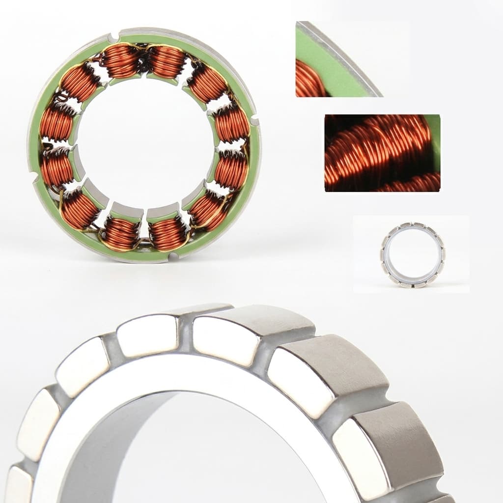
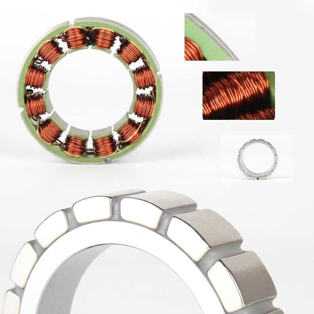
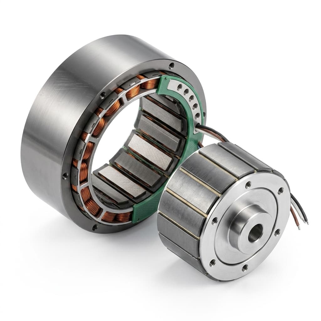
Product illustration of stator windings and a rotor magnet ring. It does not show an encoder or a measured alignment result. Mechanical angular error is multiplied by the number of motor pole pairs.
The Electromagnetic Physics: Why Commutation Offset Dictates Torque and Heat
In Field-Oriented Control (FOC) of a low-saliency permanent magnet motor below field weakening, the usual torque-per-ampere reference has current perpendicular to the rotor flux: 90° electrical, with direct-axis current Id = 0. This simplified model does not describe maximum-torque-per-ampere control of a salient motor or intentional field weakening.
For an electrical offset error δ, the commanded current is resolved incorrectly in the actual rotor coordinates. Under the sign convention used here:
T_actual = T_optimal * cos(δ)
I_q = I_stator * cos(δ)  (Torque-producing current)
I_d = -I_stator * sin(δ) (Sign depends on the angle-error convention)
Three consequences matter when interpreting test results:
- Torque at fixed current: The ratio to correctly aligned torque is cos(δ). Calculated reductions are 3.4% at 15° and 13.4% at 30°. These are torque-per-ampere changes, not percentages of input power converted to heat.
- Copper loss at equal torque: With unchanged resistance, copper loss follows the square of current magnitude. At fixed total current, rotating its d/q components does not increase copper loss. To recover the same torque, current must increase by 1/cos(δ), so the calculated copper-loss multiplier is 1/cos²(δ): approximately 1.072 at 15° and 1.333 at 30°. This excludes iron loss, saturation, thermal feedback, and current or voltage limits; it does not predict winding temperature or drive trips.
- Torque polarity and stability: In this model, torque reaches zero at 90° and reverses beyond it. There is no universal 60° load threshold or guaranteed protective trip time. Check drive protection and feedback direction before closing the motion loops.
The Pole-Pair Magnification Multiplier: Mechanical vs. Electrical Degrees
Keep mechanical degrees (θm) and electrical degrees (θe) distinct in drawings, drive settings, and inspection records.
One electrical cycle corresponds to one North/South pole pair. For P pole pairs, use:
θe = (P × θm + θoffset) modulo 360°
P = total magnetic poles / 2
Electrical angle error δe = P × mechanical angle error δm
Here θoffset is an electrical angle in the chosen coordinate convention. A drive may use a different offset sign or unit; copying a raw encoder count into an angle register is not a valid conversion.
Use the actual motor drawing for pole count. Higher pole counts multiply mechanical angular error more strongly, so identical encoder mounting tolerances produce different electrical error budgets.
The seven calculated examples below use δm = 0.5° and the fixed-current cosine model. The percentages are retained torque, not motor efficiency or measured product performance.
| Total Poles | Pole Pairs (P) | Mechanical Angle for 360° Electrical | Electrical Error from 0.5° Mechanical Misalignment | Retained Torque at Fixed Current: cos(δ) | Mechanical Error for an Illustrative 2° Electrical Budget |
|---|---|---|---|---|---|
| 2 Poles | 1 | 360.0° mech | 0.5° elec | 99.996% | 2.000° mech |
| 8 Poles | 4 | 90.0° mech | 2.0° elec | 99.94% (minimal loss) | 0.500° mech |
| 12 Poles | 6 | 60.0° mech | 3.0° elec | 99.86% (< 0.2% loss) | 0.333° mech |
| 14 Poles | 7 | 51.4° mech | 3.5° elec | 99.81% (minor loss) | 0.286° mech |
| 20 Poles | 10 | 36.0° mech | 5.0° elec | 99.62% (0.38% reduction) | 0.200° mech |
| 24 Poles | 12 | 30.0° mech | 6.0° elec | 99.45% (0.55% reduction) | 0.167° mech |
| 32 Poles | 16 | 22.5° mech | 8.0° elec | 99.03% (0.97% reduction) | 0.125° mech |
Engineering Takeaway: In a 24-pole motor (P = 12), 1.0° mechanical error becomes 12° electrical. An illustrative 2.5° mounting error becomes 30° electrical: 13.4% less torque at fixed current, or 33.3% more copper loss if the original torque is recovered within the current limit. A 2° electrical acceptance budget allows only 0.167° total mechanical angular error before allocating margin to encoder accuracy and other contributors. This is an example budget, not an industry acceptance standard.
Commutation Architecture Diagram: Electrical Zero & Phase Relations
This conceptual schematic separates phase axes, encoder offset, and a back-EMF reference event. It is not a wiring diagram or a pole-count drawing. A line-to-line voltage crossing is not interchangeable with a phase-to-neutral crossing; the chosen event must be mapped to the drive's angle convention.
6 Methods to Establish or Preserve Commutation & Electrical Zero
The first four approaches establish a reference; the fifth stores an already-established reference, and the sixth estimates initial position using a specialized drive algorithm. They are not interchangeable. Choose according to permitted startup movement, motor electromagnetic design, feedback capability, and access before gearbox assembly.
Method 1: Current-Limited DC Vector Locking (Phase Injection)
The principle: A stationary stator current vector draws an unloaded rotor toward an equilibrium. Record the encoder angle at that position, then convert it to the drive's offset convention. One common vector uses U positive with V and W tied to the negative terminal, but the supplier must confirm the connection and the corresponding magnetic reference for the actual winding.
Use a qualified station procedure:
- Mechanically support the assembly, remove external torque, and confirm clearance for the possible alignment movement. Isolate the motor phases from the inverter before connecting an external supply.
- Set current, voltage compliance, and energization duration from the motor supplier's winding and thermal limits. There is no universal safe supply voltage or percentage of rated current for every kit; define whether the current limit refers to a phase or the supply branch.
- Energize the specified vector and allow the rotor to settle. Approach from both directions using the fixture procedure; do not reposition energized hardware by hand.
- Record angle, current, duration, fixture orientation, winding temperature, and repeatability. Excessive directional spread indicates friction or load bias rather than a valid calibration.
- De-energize and convert the recorded position using the drive's pole scaling, offset sign, units, and phase convention. Reconnect and verify at limited torque before enabling position control.
Selection boundary: DC locking is useful for accessible, low-friction motor subassemblies. A brake, gearbox, seal drag, or gravity torque can bias the equilibrium. Increasing current is not a general remedy because thermal and magnet limits remain independent constraints.
Method 2: Back-EMF Alignment with a Driven Spindle and Encoder Reference
The principle: Back-drive the motor with an external spindle and compare a defined open-circuit back-EMF event with the encoder angle or index. Select a speed that gives measurable voltage within motor, fixture, and instrument limits; a fixed test speed cannot suit every motor.
Record the voltage pair, probe polarity, rotation direction, viewing face, speed, and encoder edge used. For balanced sinusoidal waveforms, line-to-line and phase-to-neutral voltages differ by 30° electrical, with sign determined by convention. Their zero crossings cannot both be treated as the same electrical-zero event. A non-sinusoidal waveform requires its own reference definition.
For constant speed, the time relationship is:
Electrical angle separation = 360° × Δt / T_electrical
Electrical frequency = P × rotational speed in rpm / 60
The separation must still be converted to the drive's flux-angle convention. A once-per-revolution index does not provide a separate index for every pole pair. With absolute feedback, latch or synchronously sample the position at the chosen voltage event.
Selection boundary: This method can independently compare phase sequence, waveform balance, and feedback alignment before gearbox installation. Precision depends on speed stability, sampling synchronization, probe behavior, and waveform quality. Metrological traceability requires calibrated instruments and an uncertainty budget; the method alone does not establish it. Isolate the inverter and use suitably rated differential measurement equipment.
Method 3: Automated Drive Alignment (Wake & Shake)
The principle: A drive applies current vectors and evaluates the resulting encoder motion. The exact sequence is a firmware feature. For example, Kollmorgen AKD Mode 0 uses a coarse search followed by refinement; current, pulse duration, movement limits, and loop settings affect the result. Follow the official AKD Wake & Shake procedure for that drive rather than transferring settings across brands.
Selection boundary: This is a candidate when startup motion is allowed. A rigid brake, end stop, friction, or external load can invalidate the measurement. For a gravity-loaded joint, use an approved support and brake sequence. A generic instruction to preload torque before commutation is known does not establish a safe startup process. Absolute feedback with a verified stored offset can avoid a motion-based search when its calibration remains valid.
Method 4: Mechanically Referenced Rotor, Stator, and Encoder Assembly
The principle: Drawing datums and fixtures preserve a supplier-established relationship between magnet axis, winding phase axis, and feedback position. A keyway or laser mark helps only when its relationship to the magnetic reference is specified and inspected. Marking a hub does not independently establish electrical zero.
Convert tangential positioning error to angle before allocating tolerances:
Mechanical angle error in degrees ≈ (tangential error / datum radius) × 180 / π
Electrical angle error ≈ P × mechanical angle error
For an illustrative 50 mm diameter datum, 0.05 mm tangential displacement gives approximately 0.115° mechanical, or 1.15° electrical for a 20-pole motor. This calculation concerns tangential angular location; radial runout and encoder eccentricity need their own error models. A drawing tolerance cannot be chosen without the datum radius and electrical error budget.
Selection boundary: Mechanical referencing can shorten repeated assembly operations, but fixture wear, magnetization variation, adhesive cure movement, and mounting repeatability still need inspection. Validate the complete process electrically before accepting it as a substitute for per-unit angle measurement.
Method 5: Store the Offset in the Drive or a Supported Absolute Encoder
The principle: First establish the relationship using a calibrated procedure. Then retain it in the drive's non-volatile configuration, or in an encoder that explicitly supports the necessary preset or offset function. Writing an offset preserves a measurement; it does not improve its accuracy.
BiSS-C, SSI, or EnDat interface names alone do not guarantee a writable electronic-zero function, a register address, or power-loss retention. Confirm the exact encoder model, firmware, programming tool, write protection, and drive behavior. Encoder position zero and the drive's commutation reference may differ even after a preset operation.
Novanta's commutation reference describes retaining a known offset with absolute feedback when the relevant motor, wiring, and mounting relationship remain unchanged. Production records should bind the motor and encoder serial numbers to the offset, pole count, direction, phase mapping, and configuration revision. Power-cycle the assembly and repeat the limited-current direction check before release.
Selection boundary: This is a practical architecture for joints where startup motion is unacceptable. Define a service rule: encoder replacement, phase rewiring, or rotor-to-sensor movement requires revalidation. Replacing a drive requires restoring and checking the correct unit-specific configuration.
Method 6: High-Frequency Injection and Initial Position Detection
The principle: Some drives estimate initial rotor position from current responses to injected signals. Initial polarity detection and continuous low-speed angle tracking are related but distinct functions. Texas Instruments explains the use of magnetic saturation for initial polarity and saliency for tracking in its IPD/HFI technical article, SSZTCJ7.
Selection boundary: Availability depends on the exact motor and drive combination. Surface-magnet or slotless construction may provide insufficient usable signal for a particular algorithm. Slotless does not automatically mean ironless. There is no universal inductance-ratio cutoff, injection frequency, or guaranteed no-motion accuracy for all frameless kits. Require vendor-supported tests across the intended current, temperature, and load range, including how polarity ambiguity is resolved.
Treat HFI as a specialized startup option until validated. A brake remaining closed during a vendor-qualified test does not establish that the subsequent torque handover is correct, nor does initial position detection alone verify encoder calibration.
Production vs. Prototyping Decision Matrix
Use this six-row matrix to shortlist a process, then request station evidence. It intentionally gives no universal accuracy, cycle-time, capital-cost, or annual-volume thresholds: those require a defined fixture, acceptance limit, automation scope, and supplier quotation.
| Method | Access or movement needed | Main uncertainty | Station resources | Evidence to request | Best initial use |
|---|---|---|---|---|---|
| DC vector lock | Free movement to an equilibrium | Friction and external torque bias | Current-limited supply or supported drive routine, fixture, feedback reader | Bidirectional repeatability and thermal limits | Accessible motor subassembly prototypes |
| Back-EMF comparison | External back-drive within approved speed | Voltage-event definition and synchronized capture | Driven spindle, differential acquisition, encoder capture | Phase convention, timing uncertainty, calibrated instruments | Independent reference characterization before gearbox closure |
| Automated drive alignment | Firmware-defined startup motion | Load, friction, loop settings | Compatible drive and commissioned feedback | Supported parameter set and startup trials | Unconstrained axes permitting measured startup movement |
| Mechanical referencing | Access during assembly | Datum and process tolerance stack | Referenced parts, fixtures, inspection | Magnetic-to-mechanical datum report and electrical correlation | Repeat production after process qualification |
| Stored absolute offset | Initial calibration access; no search if valid | Retention, configuration mismatch, later slippage | Supported drive memory or encoder programming tool | Power-cycle test, serial binding, service recovery procedure | Joints requiring repeatable startup without alignment motion |
| HFI / initial position detection | Vendor-defined injection and handover | Motor-dependent signal and polarity estimate | Explicitly supported motor-drive algorithm | Temperature/current/load tests and startup bounds | Specialized designs with demonstrated compatibility |
For production budgeting, separate the station's measurement time from handling, stabilization, programming, verification, and retest. Ask for repeatability against an independent reference, not merely identical software outputs. An offset register can report the same number repeatedly while the underlying fixture remains biased.
If your joint cannot move at startup, request an integration review with the brake sequence, motor pole count, and exact encoder model before selecting the calibration station. This helps identify which tests must happen before the gearbox or enclosure makes the rotor inaccessible.
Failure Modes & Troubleshooting in Robotic Joint Actuators
The following are diagnostic scenarios, not recorded customer incidents. Record actual motion, current, and fault logs before assigning a cause; drive fault codes and protection times vary by model.
1. Gravity-Loaded Axis Moves During Alignment
Symptom: A shoulder or elbow axis changes position during a startup search, or reports excessive movement.
Likely mechanism: External torque or an unsuitable brake sequence interferes with the motion used to infer angle. Do not assume that another drive's routine or default current will hold the payload.
Engineering response: Support or unload the axis during commissioning. Prefer an absolute motor-side reference with a verified stored offset when the application forbids startup movement. Have the machine designer qualify brake release, torque handover, and loss-of-feedback behavior. Do not use an unverified angle to generate a presumed gravity-compensation torque.
2. DC Lock Results Differ by Approach Direction
Symptom: Clockwise and counter-clockwise approaches produce different encoder readings under the same injection vector.
Likely mechanism: Friction, gearbox hysteresis, cogging, or external torque prevents a unique equilibrium. Compare the directional spread with the allocated electrical-angle budget.
Engineering response: Calibrate before coupling the gearbox when practical. If the procedure uses a midpoint, unwrap both readings around the same pole-pair equilibrium before averaging. For example, the midpoint of 359° and 1° is 0°, not 180°. Even the correct circular midpoint is only an estimate: asymmetric friction or load can retain a bias. Reject excessive spread and verify against an independent reference rather than declaring the average to be true zero.
3. Angle Error Changes Across the Mechanical Revolution
Symptom: Torque quality varies with rotor position despite an apparently correct offset at one location.
Possible causes: Incorrect pole count, encoder direction or scale, encoder cyclic error, phase mapping, or lost incremental counts. In a dual-encoder joint, also confirm that commutation uses the intended motor-side feedback; gearbox backlash and compliance make output-side position a different measurement.
A general-purpose encoder does not need a counts-per-turn value divisible by the motor pole pairs. For N decoded counts per mechanical turn, the nominal electrical step is:
Electrical step per count = 360° × P / NAs a calculated example, a 20-bit encoder has 1,048,576 counts. With P = 7, that number is not divisible by seven, yet the nominal step is about 0.0024° electrical. Resolution is not accuracy; cyclic error, latency, and the drive's numerical implementation still matter. Verify any product-specific restrictions in the drive manual.
Inspect a full mechanical turn where travel permits, logging the phase relationship and feedback continuity. A conventional once-per-turn Z index repeats at the same shaft position each revolution, not at every electrical cycle. At speed, include feedback delay in the budget: a delay of τ seconds contributes approximately 360° × electrical frequency × τ of electrical angle lag. Static electrical-zero calibration cannot remove an unknown dynamic delay.
8-Point Procurement & Engineering Quality Checklist
Use this checklist in the RFQ and acceptance plan. Numerical limits belong to the approved application error budget, not a universal motor standard.
- 1. Define the coordinate convention. State the motor viewing face, positive mechanical rotation, U/V/W phase sequence, voltage polarity, and the magnetic or back-EMF event used as reference. Record offset units and sign.
- 2. Specify magnetic-to-mechanical datums. If a rotor mark, keyway, or stator feature transfers the reference, require its measured relationship to the magnetic/winding axis and an angular tolerance at a named datum radius.
- 3. Request phase-waveform evidence. Agree test speed, voltage measurement pairs, temperature, phase balance definition, and limits. Require the actual traces and test conditions rather than an unqualified pass statement.
- 4. Freeze phase and feedback wiring. Define connector pins, shielding, feedback direction, and the exact encoder configuration. Wire colors alone do not establish a standard phase sequence.
- 5. Allocate the total electrical-angle budget. Include mounting error multiplied by pole pairs, encoder accuracy, calibration repeatability, and speed-dependent latency. For an illustrative ±2° electrical total budget at P = 12, the entire mechanical-equivalent budget is only ±0.167° before splitting contributors.
- 6. Assign calibration and storage ownership. Name the supplier or integrator responsible for the measurement, approved procedure, offset location, firmware revision, serial-number binding, and revalidation after service.
- 7. Define acceptance and power-cycle checks. Specify a reference measurement and repeatability limit, then test retained configuration after power removal. The illustrative 2° budget is not a manufacturer guarantee or industry standard.
- 8. Verify limited-current torque direction and response. On a supported, travel-limited test stand, follow the drive manufacturer's commissioning procedure in both directions before enabling normal motion. Log phase currents and an independent reference where needed: Id = 0 reported in the drive's own potentially misaligned coordinates does not prove correct magnetic alignment.
The Kollmorgen resolver commissioning guide illustrates why phase wiring, feedback conventions, and torque direction must be considered together. Its procedure is product-specific; use the corresponding documentation for your drive and feedback type.
Frequently Asked Questions (FAQ)
Q1: What is the difference between mechanical zero and electrical zero?
Mechanical zero is a chosen shaft or machine home reference. Electrical zero is a chosen rotor-flux alignment in the drive's electrical coordinate system. For P pole pairs, the magnetic relationship repeats P times per mechanical revolution. Establish the reference event, phase wiring, and sign convention before converting an encoder reading into a stored offset. A machine home preset alone does not establish commutation.
Q2: What happens with a 180° electrical offset error?
In the low-saliency model, torque reverses for the same commanded quadrature current. Closing velocity or position loops can then produce uncontrolled motion. Protection behavior depends on the drive, settings, and mechanics; do not assume an overcurrent trip will occur within a particular time. Validate direction with limited current and constrained travel before normal commissioning.
Q3: Does heat at standstill prove the electrical zero is wrong?
No. Copper loss can occur whenever the motor carries current, even though mechanical output power is zero at zero speed. Holding a gravity load, brake drag, friction, unstable tuning, current-sensor bias, and a wrong angle are possible contributors. Compare the required holding torque, actual phase currents, and thermal conditions. Offset error increases required current for a given torque in the simplified model; a sine percentage of Id is not a heat percentage.
Q4: Can Wake & Shake run with a spring-applied holding brake?
A motion-based routine needs enough permitted rotor response for its algorithm. A clamped brake can prevent that response, while releasing it on a loaded vertical joint can cause movement. Use the drive's documented brake behavior and a machine-specific supported commissioning process. For startup without a search movement, investigate absolute feedback with a previously validated offset or a specifically qualified alternative.
Q5: Does temperature change the commutation offset?
It can affect the installed measurement through encoder error, mounting movement, adhesive behavior, or mechanical slip. Copper resistance also changes, influencing heating and current-loop behavior. Do not assume that every warm motor needs a new angular offset, or that the cold calibration remains adequate. Check repeatability and alignment error over the application's specified temperature range, retaining the test conditions with the calibration record.
Q6: Can Hall sensors replace high-resolution feedback?
Three digital Hall channels generally identify six electrical sectors. They can provide coarse startup information, including a reference for transition to incremental feedback, but do not alone establish precise rotor angle throughout a sector. Smoothness and positioning requirements determine whether interpolated or higher-resolution feedback is needed. There is no universal minimum bit depth: select using electrical-angle accuracy, pole pairs, latency, speed, and the drive's supported control method.
Sources & Technical References
The following four official pages were accessed on 2026-11-05. They support the specific control concepts identified below, not product performance, station pricing, or a universal acceptance tolerance. The calculations in this article are illustrative and reproducible from the stated equations; no physical test results are claimed.
- Kollmorgen: Establishing Commutation for Resolver Based Motors with the AKD/AKD2G — identifies AKD
MOTOR.PHASE, AKD2GAXIS#.MOTOR.PHASE, and the relationship between phase wiring, feedback, and torque direction. Resolver-specific commissioning guidance. - Kollmorgen AKD Web Help: Using Wake and Shake Mode 0 (WS.MODE 0) — describes the motion-based search and its current, movement, brake, load, and friction constraints. Settings apply to the documented drive family.
- Novanta Motion, Summit Reference Manual: Commutation — explains mechanical-to-electrical angle scaling, absolute versus incremental feedback, alignment procedures, and conditions for reusing a stored offset.
- Texas Instruments, Chris Clearman: SSZTCJ7: Initial position detection and high-frequency injection — distinguishes initial polarity detection from low-speed tracking and discusses saliency and load-related limitations. This is an implementation example, not proof of compatibility with a particular frameless kit.
Request a Joint Commutation & Motor Integration Review
To review a prototype or production concept, send the motor drawing revision and pole count, encoder part number and protocol, drive model and firmware, joint travel limits, brake arrangement, and target electrical-angle error budget. Include whether the offset must survive encoder or controller replacement. Unknown requirements can be identified during the review rather than replaced with assumed specifications.
Compare the relevant component families:
- Frameless Servo Motor Kits for rotor/stator packaging and winding requirements.
- Hollow Shaft Frameless Servo Series for through-bore and feedback mounting constraints.
- Torque Motor Series for direct-drive integration options.
Contact our engineering team to discuss the proposed calibration approach and the supplier evidence needed for your acceptance plan. Any custom magnetic datum, encoder preset, fixture, or factory calibration service needs project-specific feasibility confirmation.
Author

More Posts
Back-EMF Testing for Frameless Motors: Why It Matters in Supplier Quality Control
A practical guide for OEM buyers on using Back-EMF waveform, phase difference, THD, resistance, and insulation checks to qualify frameless motor suppliers.
How to Address Cogging Torque in Frameless Servo Motors: Slotted vs. Slotless Designs
A comprehensive engineering and procurement guide to evaluating cogging torque in direct-drive frameless servo motors. Compare slotted and slotless designs for precision applications.
Frameless Servo Motor Inverter-Duty Winding Insulation & dV/dt: Managing GaN/SiC Transients, PDIV, and Bearing Currents
Specify frameless servo motor inverter-duty insulation using measured dV/dt, hot PDIV and bearing-current evidence. Use the RFQ checklist to request a review.