
Frameless Servo Motor Inverter-Duty Winding Insulation & dV/dt: Managing GaN/SiC Transients, PDIV, and Bearing Currents
Specify frameless servo motor inverter-duty insulation using measured dV/dt, hot PDIV and bearing-current evidence. Use the RFQ checklist to request a review.
Specify frameless servo motor inverter-duty winding insulation against the measured motor-terminal waveform, hot insulation behavior, and installed bearing-current paths. A thermal class alone does not establish repetitive-pulse capability. GaN or SiC transistor technology alone does not establish the stress either: bus voltage, gate settings, cable routing, filters, and winding geometry all matter.
A frameless stator/rotor kit leaves the housing, shaft, bearings, and bonding paths to the OEM assembly. Coordinate those interfaces with the motor and drive suppliers before treating a winding option as qualified. A DC high-potential test, a PDIV measurement, and an installed bearing-current assessment answer different acceptance questions.
Published and reviewed: 2026-10-28. Scope: Global OEM engineering and procurement teams integrating permanent-magnet frameless servo kits on nominal 24–600 V DC buses with PWM drives. This is a sourcing and validation framework, not a certification or a report of factory testing. The worked example uses hypothetical inputs; no universal safe dV/dt, PDIV margin, or service life is claimed. Applicable standards, supplier drawings, and an agreed test plan govern release. Revisit the review when the drive, harness, winding, or potting process changes.
For an active robot joint or direct-drive gimbal project, request an insulation and drive-interface review with your inverter bus voltage, switching frequency, gate rise times, and target operating temperatures.
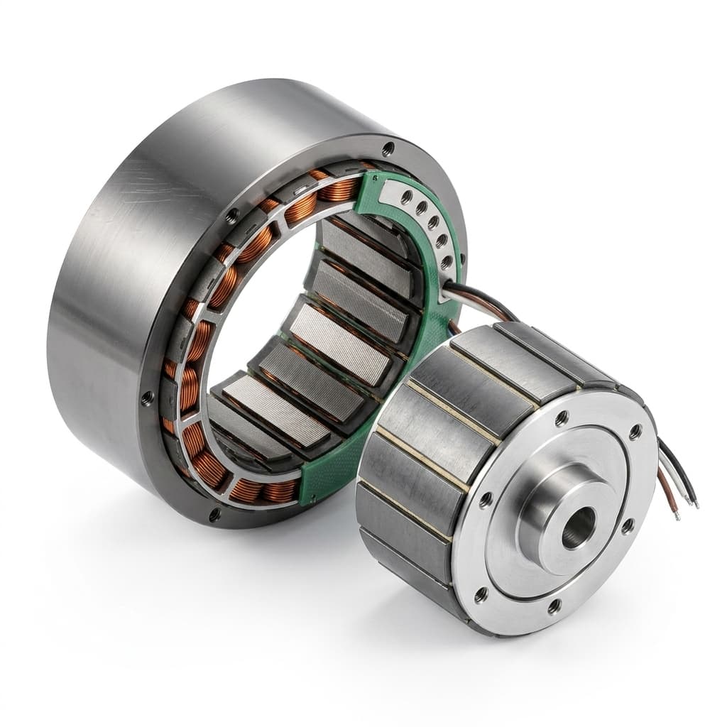
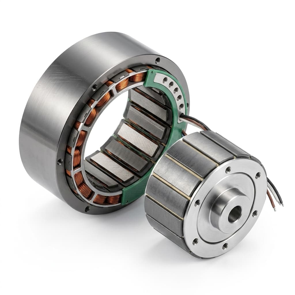
Product illustration of a stator/rotor kit; it does not identify the wire grade, internal insulation barriers, or dielectric performance.
1. High-Frequency Inverter Physics: Why Fast dV/dt Stresses Frameless Stators
Separate PWM carrier frequency from voltage edge speed. Carrier frequency describes pulse repetition; dV/dt describes how quickly each voltage edge changes. A high carrier frequency does not require the fastest possible edge. For a concrete GaN example, EPC's EPC9196 board lists a 30–170 V input range, PWM operation up to 150 kHz, and output dV/dt optimized below 10 V/ns. Those are board specifications, not insulation approval for a connected motor.
Fast edges can excite ringing and cable reflections. Measure the waveform at the motor terminals with the intended harness, maximum bus condition including regeneration, and relevant operating points. Record peak voltage, rise time, ringing, probe bandwidth, and measurement reference. A line-to-line measurement and a phase-to-frame measurement characterize different stresses.
The Non-Linear Turn-to-Turn Surge Distribution
At sufficiently low frequencies, dividing phase voltage by the number of series turns is a useful first approximation. During a fast transient, distributed winding inductance and turn-to-turn and turn-to-core capacitances influence the initial distribution. Entry turns can see greater stress than a uniform model predicts, but no fixed percentage applies to all random-wound frameless stators.
Use edge slew rate ≈ voltage change / rise time, stating the rise-time convention. For a hypothetical 48 V edge with a 10–90% rise time of 8 ns, the average slew over that interval is 0.8 × 48 / 8 = 4.8 V/ns. If ringing separately reaches 90 V, report that peak independently; do not substitute it for the edge amplitude in this calculation.
This calculation screens measurement consistency. It does not predict turn voltage, PDIV, or bearing life. An insulation model or representative winding test is needed to evaluate local turn stress.
Qualitative schematic, not measured turn voltages. Colors do not define a stress scale. The BVR expression assumes an insulating bearing film and a simplified capacitive network; C_rh denotes the rotor-to-housing path omitted from the drawing. Real grounding paths and bearing contacts can change the circuit.
2. Partial Discharge Inception Voltage (PDIV) & Magnet Wire Degradation
PDIV is the voltage at which detectable partial discharge starts under specified test conditions. Partial discharge is a localized discharge that does not fully bridge the insulation; repeated activity can damage organic insulation. It is distinct from a complete dielectric breakdown. Fast dV/dt alone does not prove that discharge occurs, especially on a low-voltage bus.
Ask for the waveform and stressed interface
A useful report identifies the specimen or winding revision, test waveform, voltage definition, rise time, repetition rate, temperature, pressure, detection method, and detection threshold. Separate turn-to-turn, phase-to-phase, and phase-to-frame evidence. A sinusoidal RMS PDIV value is not directly interchangeable with a repetitive-impulse peak value; neither should be compared blindly with a line-to-line terminal peak.
Hot PDIV needs measurement, not a fixed derating percentage
Temperature, pressure or altitude, moisture, resin condition, and winding geometry can affect inception behavior. There is no universal 20–35% hot-PDIV reduction for every winding. Paschen's law describes gas breakdown under particular conditions; it does not predict a finished stator's PDIV from bus voltage alone. A sealed cavity also does not necessarily lose gas density when heated.
For a discharge-free design, agree with the supplier how representative impulse-PDIV evidence covers the expected electrical stress and environmental extremes, including uncertainty and aging allowance. Ask which converter-fed insulation qualification route applies, such as IEC 60034-18-41 for an applicable Type I system, and confirm the edition and scope. Do not treat a wire enamel designation or an arbitrary percentage margin as system qualification.
A 48 V drive may remain below inception even when it rings. A higher-voltage drive may require different insulation or output conditioning. The decision comes from comparable test evidence and measured stress, not a universal bus-voltage cutoff.
3. High-Frequency Capacitive Bearing Currents & EDM Fluting
A kit supplied without bearings still operates with bearings in the OEM assembly. The motor supplier, drive supplier, and mechanical integrator need a shared assessment of the installed return paths.
ABB's bearing-current guide explains how converter switching couples through parasitic capacitances and how repeated electrical discharges can damage bearing surfaces. Its conventional AC-drive examples explain the mechanism; they do not establish a failure time or a protection requirement for a particular robotic joint.
A screening model, not a bearing-life prediction
For phase voltages measured against the same reference, V_cm = (V_u + V_v + V_w) / 3. A changing common-mode voltage can couple charge from the winding to the rotor and shaft. Before a bearing film conducts, a simplified capacitive model gives:
BVR = V_shaft / V_cm ≈ C_sr / (C_sr + C_rh + C_b)
Here C_sr is winding-to-rotor capacitance, C_rh is rotor-to-housing capacitance, and C_b represents the effective bearing-film capacitances in the assumed network. Conductive contacts, shaft grounding, and other assembly paths can invalidate this simple divider. Do not assign a generic BVR percentage to a crossed-roller joint.
The capacitive relation i = C × dV/dt describes displacement current while capacitance is approximately constant; it is not a model of the peak current during an EDM arc. Whether discharges occur depends on film condition, speed, lubrication, load, temperature, and the complete circuit. Noise or fluting alone is insufficient to diagnose an electrical cause. Have qualified personnel correlate shaft-voltage/current evidence with bearing inspection and operating conditions.
4. Stator Magnet Wire & Insulation Systems: Procurement Comparison
Compare the complete insulation architecture. The table is an engineering request framework, not a catalogue of certified ratings or measured supplier costs. Wire family, thermal class, or process name alone cannot supply a maximum safe dV/dt.
| Architecture or feature | Why evaluate it | Evidence to request | Selection trade-off or limitation |
|---|---|---|---|
| Conventional dual-coat magnet wire | Baseline option when measured stress is within the qualified winding envelope | Exact grade, build, thermal rating, and representative winding pulse data | A thermal rating and DC hi-pot pass do not establish pulse endurance |
| Corona-resistant magnet wire | Candidate when repetitive electrical stress warrants enhanced erosion resistance | Manufacturer's grade-specific pulse-endurance data plus complete-system qualification | Corona resistance does not make a Type I system discharge-tolerant by default |
| Thicker enamel or reinforced conductor covering | Candidate for added separation between conductors | Finished conductor diameter, bend/abrasion limits, and winding test results | Extra thickness can reduce usable copper area and alter winding manufacture |
| Slot liners and phase barriers | Separate conductors from the core and different phases from each other | Drawing showing material, thickness, coverage, creepage, and retention | Does not independently protect every adjacent turn; thickness is project-specific |
| VPI or vacuum potting | Control impregnation, voids, and mechanical support | Resin identity, cure record, process controls, and before/after qualification evidence | Process name does not guarantee a void-free winding or a fixed PDIV gain |
| Extruded or specialty high-temperature coverings | Candidate for demanding chemical or temperature environments | Grade-specific electrical, thermal, mechanical, and process-compatibility data | No generic PEEK voltage rating, slot-fill penalty, or cost multiplier applies |
| Lead insulation and exit strain relief | Protect the interface between winding, harness, and housing | Voltage/temperature ratings, bend radius, exit drawing, and chafe inspection | A robust lead does not qualify the internal winding; match ratings to actual conditions |
For thermal and manufacturing context, see the frameless servo motor stator potting guide. Electrical qualification still needs its own test evidence.
5. Inverter Technology Matrix: Match Measured Stress to a Decision
Use semiconductor technology to start the discussion, then qualify the actual drive configuration. These scenarios are decision prompts rather than universal risk rankings.
| Drive or integration scenario | Evidence that changes the decision | Motor or system action | Release boundary |
|---|---|---|---|
| Low-voltage silicon MOSFET drive | Terminal peaks and edge rates with the final harness | Evaluate the baseline winding against its qualified envelope | Low nominal bus voltage alone is insufficient evidence |
| Joint-embedded GaN drive | Actual gate settings, short-harness ringing, and common-mode waveform | Coordinate edge control and winding/lead layout | GaN does not automatically require the fastest edge or a particular wire grade |
| Higher-voltage SiC drive within this article's scope | Maximum regenerative bus condition, terminal impulses, and comparable PDIV data | Review insulation coordination and output conditioning together | No universal MW wire designation guarantees compatibility |
| Remote inverter or extended harness | Cable length/routing, impedance changes, and motor-terminal reflections | Evaluate drive-approved output filters or edge control | An input line reactor is not a substitute for a motor-side dV/dt filter |
| High PWM carrier frequency | Measured winding and drive temperatures, losses, and acoustic requirements | Balance electrical performance against thermal limits | Carrier frequency alone cannot determine insulation stress |
| Shared shaft, gearbox, or crossed-roller joint | Shaft voltage, bearing-current paths, bonding, and lubrication conditions | Assess grounding or bearing isolation with the mechanical supplier | Changing one bearing path can divert current into another component |
Before changing wire grade or adding a filter, request a drive-interface review with the terminal waveform and winding revision. This makes competing quotes easier to compare than an unqualified “inverter-duty” label.
6. Engineering Mitigation Strategies: Motor-Side vs. Drive-Side
Motor-side measures
- Define the insulation geometry. Identify slot liners, phase barriers, lead exits, and vulnerable entry turns on the drawing. Agree material compatibility, coverage, thickness, and assembly inspection with the winding manufacturer.
- Qualify the impregnation process. For VPI or potting, document resin, cure, void-control method, thermal expansion, and compatibility with enamel and adhesives. Do not assume that potting eliminates all voids or turn-to-turn stress.
- Match leads to the interface. Specify voltage, temperature, bend radius, strain relief, and chafe protection for the actual installation. An arbitrary 600 V/200°C minimum is not appropriate for every 24–600 V bus project.
Drive-side and mechanical measures
- Tune edge speed within the drive manufacturer's limits. Gate resistance or supported slew control can change ringing and electrical stress. Measure switching loss, device temperature, control behavior, and EMC after adjustment; no fixed efficiency penalty or stress reduction is promised.
- Choose the filter for the problem. Differential-mode output filtering and common-mode suppression address different paths. Check compatibility with PWM frequency, motor inductance, cable capacitance, resonance, and current-loop behavior. Do not add a core or sine filter solely from a cable-length rule.
- Coordinate bonding and bearing protection. ABB describes bonding, suitable motor cables, output filtering, and bearing insulation as possible measures. For a frameless joint, evaluate them on the complete assembly. Any shaft-grounding device needs a suitable high-frequency path and maintenance plan. Use a lubricant change only with bearing-supplier approval; conductive grease is not a universal bypass solution.
Keep feedback-interface immunity separate from winding qualification
If the selected encoder or drive-control link uses an RS-485 physical layer, include its topology, termination, common-mode operating range, and protection in interface acceptance. TI's SLLA545, RS-485 Basics Series, addresses that communication interface. It provides no motor PDIV, insulation-rating, or bearing-current test evidence. Passing a feedback-link noise test cannot establish that the winding is electrically qualified, and an insulation test cannot establish reliable feedback communication.
7. Engineering & Procurement Acceptance Checklist
Use this handoff before approving the winding drawing or releasing a pilot lot. Assign evidence owners across the motor supplier, drive supplier, and OEM integration team.
- Drive definition: Record nominal and maximum bus voltage including regeneration, PWM frequency, gate configuration, operating points, and intended harness revision.
- Terminal waveform: Capture line-to-line and phase-to-frame peaks, rise times, ringing, and measurement setup under agreed worst-case conditions.
- Insulation identity: Record exact wire grade/build, slot and phase insulation materials, lead insulation, resin, and winding/process revision; do not accept “Class H” as the complete specification.
- Qualification boundary: Agree the applicable standard and edition, specimen representativeness, environmental conditions, and the relationship between measured terminal stress and insulation-test stress.
- PDIV evidence where applicable: Specify the waveform, peak/RMS convention, stressed interface, temperature, pressure, detection threshold, and acceptance allowance. Do not apply a universal hot-derating factor.
- Routine production tests: Agree surge, dielectric-withstand, and insulation-resistance methods as appropriate, including voltage, duration, connections, discharge procedure, sampling or 100% coverage, and acceptance limits. Do not copy a generic test-voltage formula.
- Process and lot traceability: Obtain resin/cure controls, insulation material records, inspection criteria, test-equipment calibration status, and lot-linked certificates.
- Installed bearing and EMC paths: Review bonding, shielding, bearing arrangement, shaft grounding or isolation if needed, feedback-link performance, and the maintenance implications of protection measures.
For mechanical fit and clearance, see the frameless servo motor bearing selection and air gap tolerancing guide. Mechanical acceptance and electrical-current mitigation need separate evidence.
8. Frequently Asked Questions (FAQ)
Q1: Does a 48 V GaN drive automatically cause winding partial discharge?
A: No. Fast edges can cause ringing and displacement currents, but partial discharge requires the relevant local inception condition to be exceeded. Investigate measured peaks, insulation damage, contamination, lead chafing, and thermal history before assigning the cause. A low nominal bus voltage also does not prove the complete assembly is qualified.
Q2: What is the difference between thermal class and inverter-duty capability?
A: Thermal class concerns insulation thermal endurance under its specified evaluation. Inverter-duty capability needs evidence for the complete system under applicable electrical pulse stresses. Neither a thermal-class label nor a corona-resistant wire grade establishes the finished winding's PDIV or a safe dV/dt limit.
Q3: How does operating temperature affect PDIV?
A: Temperature can change material properties and discharge behavior, but there is no universal percentage reduction. Request evidence at relevant environmental extremes with the same voltage convention, specimen, and waveform. Do not convert an ambient sine-wave result into a hot repetitive-impulse rating using a simple multiplier.
Q4: Can a frameless motor kit contribute to bearing fluting when it has no bearings?
A: Yes. Its winding and rotor become part of the OEM's assembled capacitive network, which includes the shaft, housing, and bearings. Determine whether damaging electrical discharges occur in that assembly; the kit format alone neither causes nor prevents them.
Q5: When should procurement ask for corona-resistant wire?
A: When the measured stress envelope, intended life, and applicable qualification route justify evaluating it with the supplier. Request grade-specific evidence and complete-winding qualification. Bus voltage, transistor type, or cable length alone cannot select a universal NEMA MW designation or establish that partial discharge is acceptable.
Q6: Does potting eliminate dV/dt insulation failures?
A: No. A qualified potting process can improve insulation integrity and mechanical support, but it does not remove parasitic coupling, guarantee zero voids, or approve the drive interface. Verify the finished winding and installed system after process changes.
Q7: What electrical test data should procurement request before batch release?
A: Request the agreed qualification reports, routine-test records linked to the lot, material/process traceability, and explicit test conditions and limits. PDIV, surge, hi-pot, and insulation resistance assess different properties. Neither a generic hi-pot voltage nor a room-temperature pass replaces the project-specific acceptance plan.
9. Authoritative Sources & Technical References
Source identities reviewed on 2026-10-28. The comparison tables, worked arithmetic, and RFQ checklist are this article's engineering synthesis, not supplier test results. The references have distinct scopes; none certifies the proposed motor/drive assembly.
- Efficient Power Conversion: EPC9196: 35 A GaN 3-Phase Motor Drive Inverter Evaluation Board — Manufacturer specifications give an example of deliberate motor-drive dV/dt control alongside high-frequency PWM. They do not establish a connected motor's insulation rating.
- ABB: Technical Guide No. 5: Bearing Currents in Modern AC Drive Systems, Rev. C — Background on converter-related bearing-current mechanisms and mitigation. Its conventional-drive context must be adapted and validated for an OEM joint.
- Texas Instruments: RS-485 Basics Series, SLLA545 — Physical-layer communication guidance relevant only when that interface is used. This is not a winding-insulation or bearing-current report.
10. Request an Insulation & Drive-Interface Engineering Review
Share your drive model, maximum bus condition, terminal waveform if available, PWM settings, harness layout, target winding temperature, and mechanical envelope. Include the proposed winding revision and any existing test reports so the review can identify missing evidence and suitable options for supplier validation.
Explore our frameless direct-drive platforms:
- Frameless Servo Motor Kits — Stator/rotor kits for discussing winding and harness requirements.
- Hollow Shaft Frameless Servo Series — Through-bore platforms for cable-routing and joint-envelope review.
- Torque Motor Series — Direct-drive platforms for application-specific torque and integration assessment.
Contact the engineering team to align the RFQ, drawing review, and validation plan before requesting prototype lead times. Final compatibility and release remain subject to the agreed project tests.
Author

More Posts
Back-EMF Testing for Frameless Motors: Why It Matters in Supplier Quality Control
A practical guide for OEM buyers on using Back-EMF waveform, phase difference, THD, resistance, and insulation checks to qualify frameless motor suppliers.
Frameless Servo Motor Thermal Sensor Selection & Placement: PT1000 vs. NTC vs. PTC in High-Density Joint Actuators
Specify frameless servo motor thermal sensors: compare PT1000, NTC, PTC, end-turn placement, thermal time constants, and RFQ dielectric insulation requirements.
How to Address Cogging Torque in Frameless Servo Motors: Slotted vs. Slotless Designs
A comprehensive engineering and procurement guide to evaluating cogging torque in direct-drive frameless servo motors. Compare slotted and slotless designs for precision applications.