
Integrated Power-Off Holding Brakes in Frameless Servo Motor Joints: Spring-Applied vs. Permanent Magnet Brakes in Hollow-Shaft Architectures
Compare frameless servo motor holding brakes: spring-applied vs. permanent magnet. Check hot torque, backlash and drive limits, then plan your engineering RFQ.
For a frameless servo motor joint, select a power-off holding brake by its guaranteed hot holding torque, allowable lost motion, hollow-bore fit, and approved coil drive. PM brakes are candidates for compact, backlash-free connections; spring-applied designs offer a broad choice of holding and dynamic-braking variants. Neither technology alone establishes emergency-stop capability or machine safety.
Unlike a housed motor supplied with a matched brake, a frameless kit leaves the OEM responsible for the shared housing, bearing datums, heat paths, and brake control sequence. Brake coil heat can reduce motor thermal headroom; the amount depends on the actual assembly and duty cycle.
Published and reviewed: 2026-11-01. Scope: Global, English-language guidance for OEM engineers and buyers integrating hollow-shaft frameless servo joints. The brake supply must match its coil and controller rating; the motor DC bus is not automatically a suitable brake supply. This is a component-selection and RFQ framework, not a certified safety design. Numerical examples are illustrative calculations, not measured product performance. Medical and surgical systems require their own applicable safety framework.
For collaborative robot joints, surgical manipulators, or pan-tilt gimbal designs requiring hollow-bore mechanical integration, request a joint packaging and thermal co-design review with your motor outer diameter (OD), inner bore clearance, gravity payload torque, and operating duty cycle.
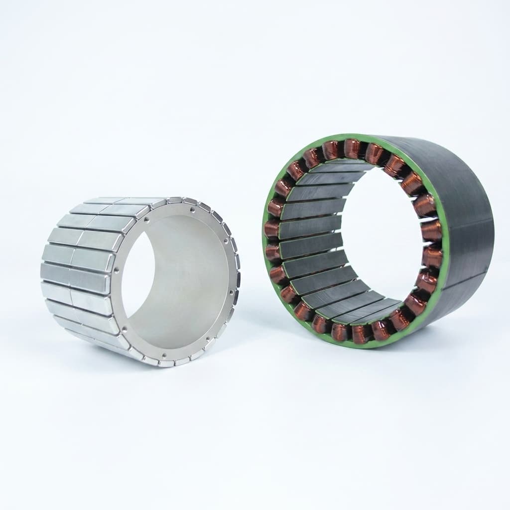
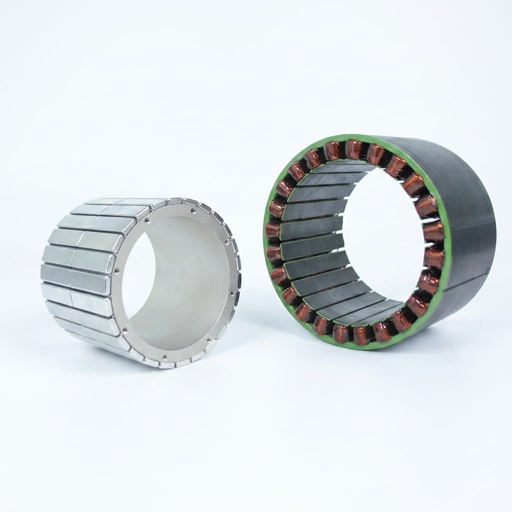
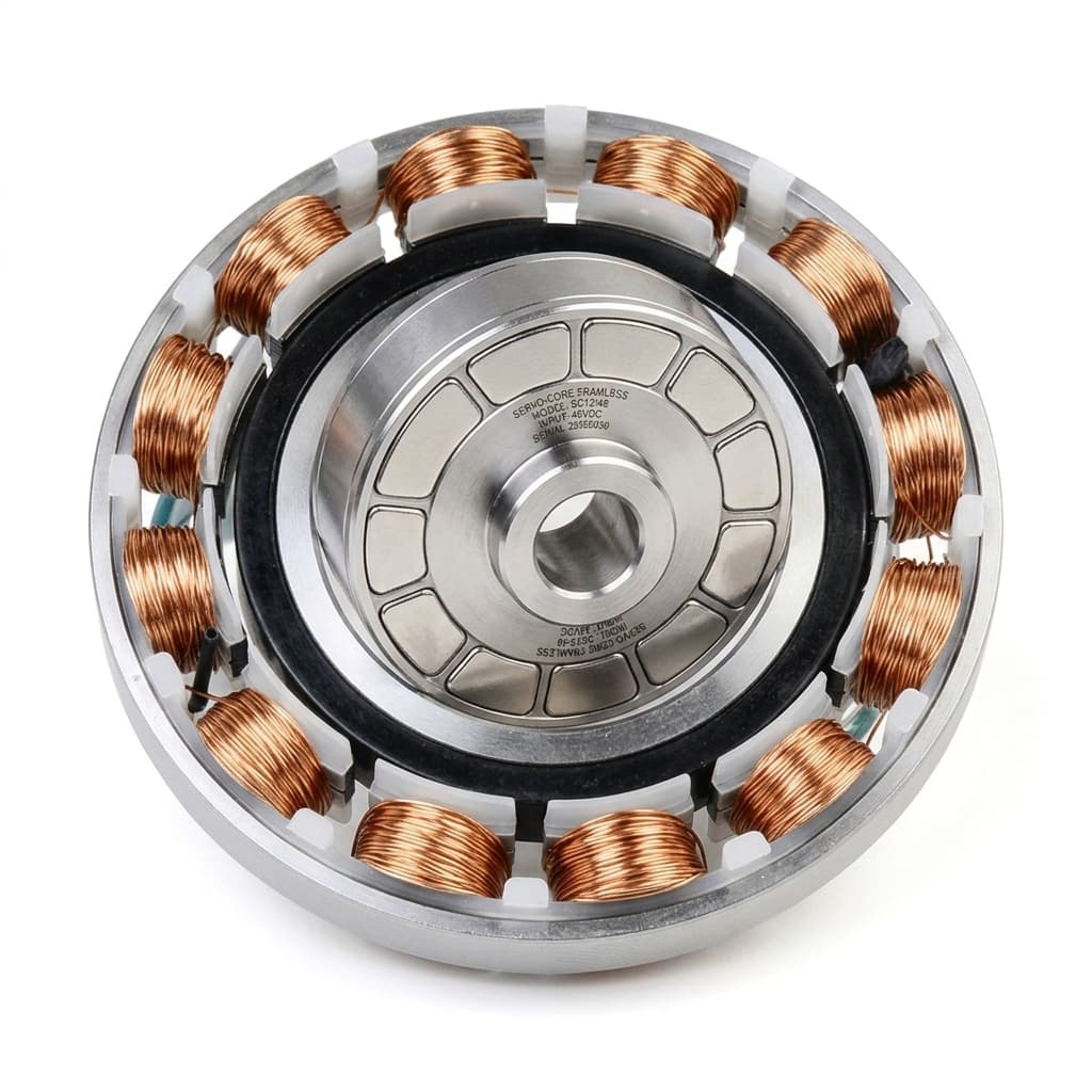
Figure 1: Frameless rotor and wound stator kit illustrating the central packaging aperture. A brake, bearing, encoder, and completed joint housing are not shown; this image does not establish brake integration or test results.
1. Safety Scope & The Joint Architecture Problem
For industrial robots, ISO 10218-1:2025 addresses robot safety; robot application and cell integration fall under Part 2. The public standard summary does not establish a universal brake torque margin, performance level, test interval, or stopping time. Medical robots are outside Part 1's scope.
Before choosing a brake, define three separate requirements:
- Unpowered holding: Prevent hazardous movement under the worst gravity load, including a loss of supply.
- Stopping: Decide whether the drive decelerates first or the brake must absorb moving-load energy. Safe torque off removes motor torque; it does not mechanically hold an axis.
- Safety validation: Use the machine risk assessment to determine redundancy, diagnostics, reliability evidence, and test intervals. A power-off component is not sufficient evidence of a validated safety function.
Why Frameless Joint Brakes Differ from Standard Motor Brakes
In conventional servo motors, the holding brake mounts to the rear motor end-bell. In high-density robotic joints, collaborative robots (cobots), and surgical arms, an axial end-bell arrangement adds excessive lever arm length and inertia. Instead, robotic architects rely on concentric hollow-shaft packaging.
A concentric joint nests the frameless stator and rotor, the cross-roller bearing, the high-resolution position encoder, and the power-off brake around a common central aperture. This hollow bore routes multi-conductor DC power lines, high-speed Industrial Ethernet (EtherCAT/Profinet), pneumatic hoses, or optical fibers straight through the center of the joint.
This spatial compression creates three fundamental engineering trade-offs:
- Shared Thermal Sink: An energized release coil dissipates resistive heat (
I²R). Its mounting path can heat the motor windings and magnets as well as the housing. - Debris Proximity: Friction wear can contaminate the motor air gap or encoder. Ferromagnetic debris is attracted to the rotor magnets; other dust can migrate through airflow, vibration, or contact.
- Backlash vs. Envelope: Lost motion and torsional compliance both contribute to tool-center-point (TCP) movement. Specify the permitted movement and mounting tolerances rather than assuming either brake family is universally backlash-free.
2. Operating Physics: Spring-Applied vs. Permanent Magnet Brakes
When selecting a power-off holding brake for a frameless joint, compare Spring-Applied Brakes (SEB) and Permanent Magnet (PM) Brakes. The schematic shows representative mechanisms, not dimensions or approved drive settings for a particular product.
2.1 Permanent Magnet Brakes: Backlash-Free Connections & Compact Packaging
A PM brake uses permanent magnets to clamp its armature when electrical power is absent. An energized coil produces an opposing field, reducing attraction so a spring can lift the armature away. A diaphragm connection can transmit torque without rotational clearance, although the complete joint still has elastic deflection.
Kendrion's PM brake overview describes compact servo applications and backlash-free shaft-hub connections. Its emergency-stop capability is product-specific; PM technology is not restricted to static holding alone.
PM drive boundary: Release depends on staying inside the manufacturer's voltage/current window across temperature and air-gap variation. Too little counter-field can leave drag; excessive current can also prevent proper release in some designs. Do not apply a spring-brake boost pulse or reduced holding current to a PM brake without written approval for that model.
2.2 Spring-Applied Brakes: Choose the Friction and Hub Variant
Mechanical springs press a friction rotor against stationary surfaces when unpowered. Energizing the coil attracts the armature against the springs and releases the friction rotor. A conventional splined hub needs clearance for axial movement; special hub or diaphragm arrangements can reduce or remove rotational play.
Mayr's ROBA-stop M product page distinguishes holding-brake and dynamic-brake versions and lists a backlash-free option. A holding version's occasional emergency-stop capability does not establish a rating for repeated production braking. This catalog family illustrates the distinction; it is not a drop-in recommendation for a hollow-shaft joint.
Selection boundary: Obtain permitted friction work per stop, total lifetime work, stop speed, and recovery interval for the exact variant. Apply this requirement to both PM and spring-applied brakes. Neither brake mechanism alone establishes a dynamic energy rating or a universal backlash value.
3. Engineering & Procurement Comparison Matrix
Use these eight dimensions to compare actual part numbers. The entries describe mechanisms and evidence to request, not universal product specifications.
| Engineering Dimension | Permanent Magnet (PM) Brake | Spring-Applied (SEB) Brake | Engineering Impact & Procurement Verification Rule |
|---|---|---|---|
| Torque and envelope | Compact magnetic clamping designs are available. | Available in many friction-disc and joint-specific layouts. | Compare minimum hot holding torque, bore, OD and axial stack from dimensioned drawings; do not assume a fixed size advantage. |
| Torsional backlash | A diaphragm connection can remove shaft-hub clearance. | Splined hubs may have play; backlash-free variants also exist. | Request angular lost motion and torsional stiffness at the brake shaft, then translate these into TCP movement. |
| Friction pairing and wear | Friction material and emergency-stop wear depend on design. | Holding and dynamic-duty linings have different ratings. | Request wear limits, contamination controls and permitted friction work for the selected variant. |
| Release supply | Opposing-field release has a specified operating window. | Coil must overcome springs at worst-case temperature and gap. | Specify terminal voltage/current, polarity, cable drop and temperature limits; do not substitute motor-bus voltage. |
| Working air gap | Controlled armature travel and alignment are important. | Permitted gap and wear adjustment depend on construction. | Use supplier gap, runout and end-play tolerances rather than a generic machining number. |
| Temperature behavior | Magnet system, friction surfaces and coil all affect operation. | Friction, spring behavior and coil heating also require validation. | Require guaranteed hot holding torque and release performance over the complete declared temperature range. |
| Dynamic emergency stops | Some models have substantial emergency-stop capacity. | Choose a holding or dynamic-braking version to match duty. | Check energy per stop, speed, cumulative work, interval and wear limits for both families. |
| Commercial comparison | Precision mounting and controller requirements affect total cost. | Hub, monitoring and lining options affect total cost. | Quote the same torque, bore, duty, monitoring and acceptance scope; include integration and maintenance costs. |
Worked Static Sizing Example: Keep the Brake Shaft Explicit
The following is an illustrative direct-drive calculation, not a tested actuator or a universal safety factor. Assume a 12 kg payload at a worst-case horizontal lever arm of 0.35 m, plus 9 Nm of link gravity torque. Assume the brake acts directly on the output shaft and the project engineer chooses a preliminary margin of 1.8:
Payload torque = mass × gravity × lever arm
               = 12 × 9.81 × 0.35 = 41.202 Nm
Total gravity torque = 41.202 + 9 = 50.202 Nm
Required minimum hot holding torque = 1.8 × 50.202 = 90.3636 Nm
A candidate needs a guaranteed minimum holding torque of at least 90.4 Nm at the declared hot condition for this screening example. A catalog's nominal room-temperature torque is insufficient evidence. The chosen margin must be justified by the actual risk assessment and supplier tolerances.
For a brake on the motor side of a reducer, establish the reverse load path, ratio, backdriving behavior, and failure assumptions before translating output torque. This direct-drive result cannot be copied to that shaft. Dynamic sizing separately starts with E_rot = 0.5 × J_equivalent × angular_speed², with inertia referred to the brake shaft; include gravitational work during descent and the actual motor/brake stopping sequence.
If the shaft location or hot torque guarantee is missing from a quote, send the joint layout and load assumptions for an engineering review before comparing unit prices.
4. Thermal Cross-Coupling in the Shared Housing
A common procurement error is pairing a standalone motor torque curve with a brake catalog rating without accounting for their shared heat path. Validate the released brake and loaded motor together inside the intended housing.
4.1 The Dual-Heat Source Problem
An IP rating describes ingress protection; it does not establish a cooling method or thermal resistance. Record the housing material, mounting contact, cooling arrangement, ambient range, and motion duty.
For a balanced three-phase motor, copper loss is P_motor = 3 × I_phase,rms² × R_phase(T), using phase rather than line resistance. Brake coil loss is P_brake = I_coil,rms² × R_coil(T); for steady DC it can also be written V_coil² / R_coil(T). Use coil terminal voltage, not an unrelated main bus.
Illustrative electrical example: A coil measuring 24 ohms at the specified condition dissipates 24 W at 24 V DC. This is arithmetic, not the typical consumption of a particular brake size. Converting those watts into a motor temperature rise requires a measured or validated thermal path; housing diameter alone cannot supply that conversion or a continuous-torque derating percentage.
4.2 Hot Holding Torque Is a Product Guarantee
A magnet material's remanence coefficient is not a brake torque coefficient. Magnetic circuit geometry, saturation, friction coefficient, magnet grade, and thermal compensation all affect hot torque. Request the selected brake's minimum holding torque across its approved temperature range, with the conditioning and wear state stated.
The acceptance decision should compare that guaranteed minimum with the required torque at the same shaft. Do not derive a universal percentage torque loss from a generic NdFeB property, or extrapolate a brake beyond its operating temperature rating.
4.3 Copper Resistance and the Release Window
As an illustrative copper-coil estimate near room temperature, use R(T) ≈ R_20 × [1 + 0.00393 × (T - 20)], with temperature in °C. For a hypothetical rise from 20°C to 120°C, resistance becomes 1.393 × R_20, and fixed-voltage current becomes 1 / 1.393 ≈ 0.718 of its initial value.
This calculation explains why hot-coil testing matters. It does not prove a 120°C coil rating, PM release failure, or a need to increase voltage: the magnet circuit also changes with temperature. Test release and residual drag at the supplier's hot/cold limits with the minimum and maximum permitted supply, including cable drop.
5. Control Circuitry: Separate Spring-Brake and PM Drive Rules
A controller must match the selected brake mechanism. Boost-and-reduce control can be useful for an approved spring-applied brake, where pull-in requires more magnetic force than maintaining the released state. A PM brake needs its specified counter-field; copying the same reduction can cause drag or re-engagement.
5.1 Pull-In and Overexcitation
For a spring-applied model that explicitly supports overexcitation, use the manufacturer's approved boost amplitude, duration, duty, and controller. Confirm that release completes before applying the motion command. Do not prescribe a fixed multiplier of nominal voltage for either brake family.
For a PM brake, follow its specified polarity and voltage/current range throughout release and motion. Obtain explicit model approval before using any boost, PWM, or current-regulation scheme.
5.2 PWM Economizers: Measure RMS Current
For an approved spring-brake economizer, calculate copper loss from RMS coil current, not from PWM duty alone:
P_copper = I_rms² × R(T)
If I_rms is halved at the same resistance:
P_reduced / P_original = (0.5)² = 0.25
The 75% reduction in this idealized calculation applies to halved RMS current, not automatically to 50% PWM duty or half the arithmetic average voltage. Inductance, ripple, switching frequency, and the recirculation circuit determine actual current. Confirm the minimum current needed to remain released under vibration and temperature variation. A lower coil loss does not, by itself, prove that the motor retains its full catalog torque.
5.3 Turn-Off and Gravity Movement
A freewheeling diode can prolong coil current decay. An appropriately designed higher-voltage clamp can accelerate decay, but semiconductor, coil insulation, EMC, and controller ratings limit the circuit. Changing suppression requires brake and drive supplier approval.
Current decay time is only part of the interval to developed holding torque; armature travel and friction engagement also matter. Record the complete sequence from stop request through drive deceleration, brake command, torque development, and motor torque removal. Check both normal stopping and loss of supply under the worst gravity load. No generic clamp voltage or millisecond target guarantees zero sag.
6. Mechanical Stack-up, Concentricity & Debris Containment
6.1 Runout, Clearance and Joint Lost Motion
Use the selected brake's installation drawing to allocate mounting-face runout, concentricity, shaft end-play, working air gap, and thermal expansion. The brake torque reaction must transfer into the structural housing; coil location alone does not define that load path. Check the harness swept envelope throughout joint rotation, not just the static bore diameter.
A zero-clearance brake hub does not eliminate housing, shaft, bearing, or reducer compliance. As a simple geometric illustration, 0.5° of joint angular movement at a 1,000 mm lever arm produces 1,000 × sin(0.5°) ≈ 8.7 mm of tip movement. This assumed angle illustrates the sensitivity; it is not a typical spring-brake backlash specification.
6.2 Wear Debris and Isolation Barriers
Either brake family can generate debris when friction surfaces engage during motion. Ferromagnetic particles may collect near rotor magnets; conductive or nonmagnetic particles can also abrade insulation, contaminate encoders, or enter the air gap through other transport paths. Conductivity alone does not imply magnetic attraction.
Review partitions, labyrinths, suitable seals, and a cleaning/inspection procedure against the actual lining material and duty. A nonmagnetic baffle is a physical partition, not a magnetic shield or an automatic dust-tight seal. Check leakage paths, seal friction and service access, and inspect after the specified dynamic-stop endurance test.
7. Actionable RFQ & Factory Acceptance Checklist
Use this checklist to align the motor supplier, brake vendor, mechanical designer, and drive integrator. Preserve unknowns in the RFQ rather than replacing them with assumed catalog defaults.
Phase A: Sizing & Load Verification
- Brake shaft and load path: State whether the brake acts at the motor or joint output, reducer ratio if present, worst gravity posture, payload and link masses, and credible transmission failures.
- Minimum hot holding torque: State the required torque, chosen project margin and rationale, temperature range, wear state, and supplier-guaranteed minimum. The worked example's margin is not a universal requirement.
- Dynamic-stop duty: Specify equivalent inertia at the brake shaft, initial speed, gravitational work, stop frequency, lifetime events, and permitted movement. Obtain both per-stop and cumulative friction-work limits.
Phase B: Electromechanical & Drive Interface
- Hollow bore and packaging: Provide brake/motor OD, ID and stack limits, harness swept envelope, mounting datums, and structural torque-reaction path.
- Release window: Obtain approved coil terminal voltage/current and polarity at hot/cold limits, including cable drop, supply tolerance and residual-drag acceptance. Keep PM and spring-brake requirements separate.
- Economizer compatibility: Require written model approval and settings for any boost, reduced-current or PWM operation. Include switching frequency, RMS current, release confirmation, and vibration checks.
- Turn-off behavior: Agree the suppression circuit and component ratings, then measure command-to-developed-torque timing in the assembled joint. Confirm stop and power-loss movement limits.
Phase C: Mechanical Integration & Quality Assurance
- Contamination control: Document the partition/seal design and post-endurance inspection for friction debris near the motor and encoder.
- Lost motion and stiffness: Specify both brake-shaft angular clearance and allowable tool displacement under load, including the remaining transmission.
- Drawing and thermal acceptance: Use supplier runout/end-play limits and verify hot holding, hot/cold release, residual drag, coil temperature and motor temperature with the intended housing and duty.
- Brake test protocol: Define a guarded holding-torque proof test, diagnostic coverage, interval and rejection criteria with the safety engineer. Record traceable test conditions; an ordinary commissioning torque check does not establish a safety-rated diagnostic function.
8. Frequently Asked Questions (FAQ)
Can a frameless motor alone hold position without an electromechanical brake?
An energized servo can hold position, but that torque is unavailable after power loss or torque removal. A gravity axis needs a risk-assessed method of preventing hazardous movement, such as a suitably controlled brake or another load-restraint arrangement. The required safety architecture depends on the machine; a brake alone does not establish compliance.
Are permanent magnet brakes always backlash-free, and spring-applied brakes always loose?
No. PM diaphragm designs can provide backlash-free shaft-hub connections, and spring-applied products also offer backlash-free options. Compare the complete connection and torsional stiffness of the exact variant. Neither eliminates elastic movement elsewhere in the joint.
Can I use a PWM economizer with a permanent magnet brake?
Only if the brake manufacturer approves the specific controller and settings. PM release requires an opposing field within a defined operating window; a generic spring-brake reduced-current scheme can cause drag or re-engagement. For an approved economizer, use measured RMS current to estimate copper loss.
Can a holding brake also perform emergency stops?
Some models permit occasional dynamic stops, including PM designs. Obtain the allowed speed, energy per stop, total friction work and recovery interval for the exact model. A repeated-braking duty may require a different variant even when its static holding torque looks sufficient.
What causes a joint to sag during an emergency stop even with a brake installed?
Possible causes include command sequencing, coil current decay, mechanical engagement delay, insufficient hot torque, lost motion, or transmission compliance. Measure the full stop sequence under the worst load before changing the suppression circuit. A faster current decay alone does not establish zero movement.
How does friction dust affect a frameless servo motor?
Wear particles can contaminate the motor air gap or encoder and abrade insulation. Rotor magnets attract ferromagnetic debris; other particles can migrate through vibration or airflow. Use a suitable containment design and inspect the actual assembly after the declared stop duty.
9. Next Steps for OEM Mechatronics Programs
Shortlist a PM or spring-applied brake against the same minimum hot torque, permitted movement, hollow-bore envelope, thermal conditions and stop duty. Then confirm the variant's mounting and controller requirements before freezing the joint design. A compact PM connection may suit a precision joint; a spring-applied holding or dynamic version may suit another axis. Either choice needs product-specific evidence.
For a robotic arm or direct-drive joint review, provide:
- Mechanical layout: Brake shaft location, motor/brake OD and bore, axial stack, bearing datums, and harness routing.
- Load and thermal duty: Gravity torque, speed, equivalent inertia, stop sequence, housing/cooling assumptions, and hot/cold limits.
- Supplier evidence: Candidate brake drawing, minimum hot torque, release-current window, dynamic work limits, and intended drive circuit.
Submit your joint specifications for an engineering review, or review the Frameless Servo Motor Kits technical-pack resources for the motor-side dimensional and RFQ baseline. Motor kit information does not establish an approved integrated brake assembly.
Sources & Technical References
Sources checked on 2026-11-01. These public pages support the product-family and scope distinctions below; numerical examples in this article are illustrative engineering arithmetic. Final limits require the selected model's current datasheet, installation instructions and application approval.
- Kendrion — Permanent Magnet Brakes: PM servo-brake families, backlash-free connections and product-dependent emergency-stop capability.
- Mayr — ROBA-stop M: Holding versus dynamic variants, emergency-stop suitability and backlash-free options. This page is a catalog example, not proof of hollow-shaft fit.
- ISO 10218-1:2025 — Robotics — Safety requirements — Part 1: Industrial robots: Public scope summary for industrial robot safety, including the distinction from Part 2 integration and the exclusion of medical robots. No clause-level compliance or universal brake parameter is inferred from the summary.
Author

More Posts
Frameless Servo Motor Bearing Selection & Air Gap Tolerancing: Preventing Eccentricity and UMP
Compare frameless servo motor bearing selection, air gap tolerance budgets, and UMP risks. Use the engineering checklist to request a supplier drawing review.
Back-EMF Testing for Frameless Motors: Why It Matters in Supplier Quality Control
A practical guide for OEM buyers on using Back-EMF waveform, phase difference, THD, resistance, and insulation checks to qualify frameless motor suppliers.
Frameless Servo Motor Rotor Mounting: Press Fit, Shrink Fit, or Gluing?
Compare frameless servo motor rotor mounting methods: gluing, press fit, and shrink fit, with torque risks, tolerances, QC checks, and RFQ guidance for OEMs.