
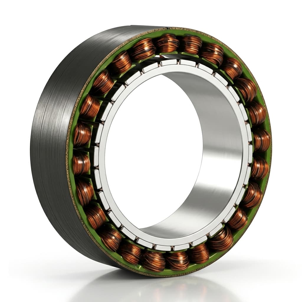
Frameless Servo Motor Bearing Selection & Air Gap Tolerancing: Preventing Eccentricity and UMP
Compare frameless servo motor bearing selection, air gap tolerance budgets, and UMP risks. Use the engineering checklist to request a supplier drawing review.
Frameless servo motor bearing selection starts with the loaded, hot assembly air gap. Use a crossed roller bearing when compact moment support is the priority; evaluate a spaced angular contact pair when speed, friction, and available bearing span favor it. Release either arrangement only after checking the selected bearing's stiffness, fits, preload, and runout against the motor drawing.
A frameless stator/rotor kit leaves the shaft, housing, and bearings to the OEM. The support system must maintain clearance between the rotor outer surface and stator bore under manufacturing variation, load, and temperature. An off-center rotor can produce unbalanced magnetic pull (UMP) toward the smaller gap, increasing bearing load and the risk of rubbing.
Published and reviewed: 2026-10-26. Scope: Global OEM engineering, sourcing, and quality teams integrating inner-rotor, radial-flux permanent-magnet frameless motors. This guide does not cover outer-rotor or axial-flux clearance geometry, air bearings, or medical/aerospace qualification. Numerical examples are illustrative calculations, not measured factory results or universal acceptance limits. The selected motor and bearing drawings govern release.
For an active design, request a bearing-interface drawing review with your motor frame, bearing arrangement, load cases, speed, and temperature range.
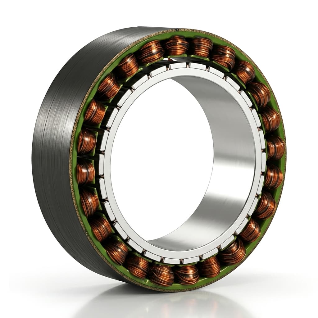
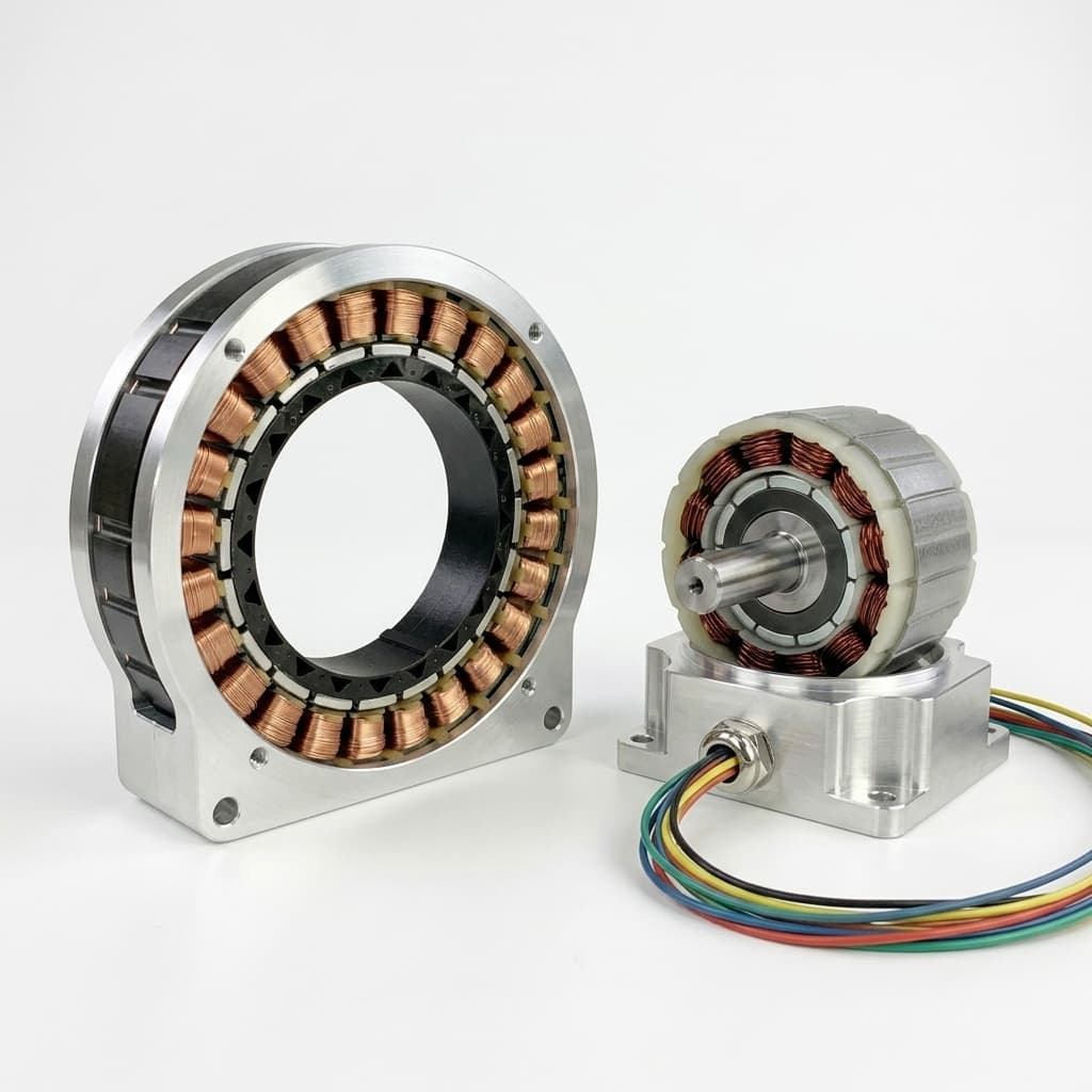
Product illustration for orientation; it is not a bearing section or dimensional inspection record.
The Air Gap Physics: Static vs. Dynamic Eccentricity
To size bearings and define machining tolerances, you must first distinguish between the two primary forms of rotor-stator misalignment: static eccentricity and dynamic eccentricity.
Schematic: an offset reduces clearance on one side. Force arrows indicate direction, not magnitude; eccentricity alone does not establish instability. Scroll horizontally on small screens.
1. Static Eccentricity (SE)
The rotation axis is offset from the stator bore axis by a fixed displacement, e_static. The smallest gap remains stationary relative to the housing. Possible causes include bearing-seat/stator-seat misalignment, datum shift between machining setups, and mounting distortion.
2. Dynamic Eccentricity (DE)
The rotor's geometric center is displaced from its rotation axis by e_dynamic, so the smallest gap rotates with the shaft. Rotor mounting runout or a rotating shaft bow can contribute. A housing-fixed cantilever load can instead produce a stationary deflection: classify the displacement by its motion relative to the stator, not just its cause.
3. Mixed Eccentricity (The Real-World Condition)
An assembly can combine static and rotating offsets. In a simplified circular, parallel-axis model, a conservative geometric bound is:
e_peak ≤ |e_static| + |e_dynamic|
gap_min ≥ gap_0 − (|e_static| + |e_dynamic|)
Here gap_0 is nominal radial clearance. A release calculation must additionally include size tolerances, tilt along the active length, form error, thermal distortion, and load deflection. A positive geometric gap does not by itself establish magnetic stability.
Vibration and current harmonics can help diagnosis, but their frequencies depend on pole/slot combination, winding, speed, and control. Do not use one spectral peak as proof of a particular eccentricity mode. Chen et al. (2017) describe a PMSM UMP model checked against finite-element analysis and experiments; their EV motor results are not universal frameless-motor limits.
Unbalanced Magnetic Pull (UMP): The Negative Spring Phenomenon
Permanent magnets can produce radial attraction even with the drive unpowered. Eccentricity changes the magnetic field around the circumference, creating a resultant load that the bearing, shaft, and housing system must resist.
The Non-Linear Force Scaling
For a predominantly radial field, a simplified local magnetic pressure estimate is:
pressure ≈ B_radial² / (2 μ₀)
B_radial is in tesla, μ₀ ≈ 4π × 10⁻⁷ H/m, and pressure is in pascals. Net UMP requires integrating the field stresses around the rotor surface, including tangential-field terms where significant. This local expression is not a motor force prediction.
Magnetic pressure scales with the square of flux density. The relationship between gap and flux is design dependent and can be nonlinear; it is not generally exponential. Request a force-versus-offset curve over the required current, rotor-angle, and temperature cases instead of assigning an arbitrary UMP load.
In the ideal symmetric model, opposite radial forces cancel. With eccentricity, stronger attraction on the narrow side can pull the rotor farther off-center.
UMP Acts as a Negative Mechanical Spring
Define K_mag = dF_UMP/de > 0 as the local destabilizing force slope, in N/mm, and K_support > 0 as the restoring stiffness of the complete bearing/shaft/housing load path at the rotor:
K_effective = K_support − K_mag
Positive effective stiffness is a necessary local static screening condition in this one-direction linearization. It is not a complete stability proof: moment compliance, bearing nonlinearities, damping, resonances, and the full operating envelope still require evaluation. A high bearing catalogue stiffness alone cannot compensate for a flexible shaft or housing.
Impact on Bearing Fatigue Life (L10h)
For constant speed and equivalent load, the basic rating-life relationship is:
L10h = [10⁶ / (60 n)] × (C/P)^p
C and P must use the same force units; n is rpm. The exponent is 3 for ball bearings and 10/3 for roller bearings. Basic L10 life represents 90% survival against rolling-contact fatigue under the model assumptions. SKF's explanation of rolling bearing life also discusses reliability and operating-condition adjustments.
Illustrative sensitivity: if a ball bearing's equivalent load rises from 1,000 N to 1,500 N at unchanged speed, its basic life ratio is (1000/1500)³ = 0.296, about 70% lower. This is arithmetic, not a measured UMP result. Resolve external and magnetic forces through the bearing arrangement before calculating P; do not simply add their magnitudes. Oscillating robot joints also need supplier checks for lubrication, wear, static loading, and small-angle motion. Electrical fluting requires a separate electrical-current investigation.
Bearing Architecture Comparison: Selecting the Right Topology
Because the frameless motor kit provides no bearings, the OEM design team must select a bearing topology that matches the application's axial envelope, tilting moment stiffness, rotational speed, and budget.
The six options below support an initial design shortlist. Stiffness and friction descriptions are qualitative tendencies, not equal-size test results. No topology has a universal rpm limit: confirm the selected part's speed, lubrication, preload, fit, and load ratings.
| Bearing Topology | Radial Stiffness | Axial Load Capacity | Tilting Moment Stiffness | Axial Space Envelope | Speed Selection Check | Friction Torque & Heat | Assembly & Preload Sensitivity | Typical Application Boundary |
|---|---|---|---|---|---|---|---|---|
| Crossed roller bearing | High with adequate support | Bidirectional | Compact moment support | Short single ring | Check ring diameter, seals, and permissible speed | Preload and seals affect heat | Seat form and clamping distortion matter | Compact robot joints and rotary tables |
| Duplex angular contact ball, back-to-back (DB) | Preload dependent | Bidirectional pair | Larger effective load-center spread than comparable DF | Allow room for pair and span | Check matched-pair rating at operating preload | Often favorable for speed; verify losses | Match orientation, spacers, and clamp load | Spindles or axes with available bearing span |
| Duplex angular contact ball, face-to-face (DF) | Preload dependent | Bidirectional pair | Smaller effective spread than comparable DB | Pair and spacers | Check part and preload rating | Contact angle and lubrication matter | More tolerant of some mounting misalignment; not self-aligning | Axes where mounting geometry favors DF |
| Thin-section four-point contact ball | Support and contact dependent | Combined-load capability; verify limits | Check moment load and ring deflection | Small section, large bore | Check combined-load friction and allowable speed | May rise under combined loading | Thin rings follow housing form error | Hollow-bore gimbals and space-limited axes |
| Deep-groove ball bearing pair | Clearance, fit, and span dependent | Limited by selected part and arrangement | Can be adequate with suitable span | Two support stations | Check actual part rating | Often low; seals and preload add losses | Evaluate operating clearance and axial location | Viable when calculated clearance and stiffness meet the axis budget |
| Integrated angular contact roller ring | Supplier curve required | Combined-load design dependent | Evaluate moment curve | Compact integrated support | Check lubrication and duty-specific limits | Verify starting and running torque | Requires supplier-defined mounting support | High-load joints after part-specific review |
Deep-Dive Analysis of the Top Two Choices
1. Crossed Roller Bearings (CRBs) for Robotics Joints
For a compact robot joint, compare the complete bearing support envelope and moment-deflection curve. A spaced pair resists an applied moment through bearing reactions; a crossed roller ring can provide combined radial, axial, and moment support within one ring.
THK's Cross-Roller Ring documentation explains its perpendicular roller arrangement and combined-load capability. This supports the architecture choice, but not a universal stiffness multiplier or percentage reduction in joint length.
Drawing check: specify seat roundness, cylindricity, shoulder geometry, and bolt tightening according to the selected bearing manual. ISO IT size grades do not by themselves specify cylindrical form error. Measure assembled running torque as well as seat dimensions.
2. Preloaded Duplex Angular Contact Ball Bearings (DB) for High Speed
Evaluate a DB ball-bearing pair when speed and friction favor it and space permits adequate support span. Its outward-diverging contact lines give a larger effective load-center spread than a comparable DF pair. Select the matched pair, preload class, spacers, fits, and locking method together. Confirm hot running torque and temperature; increasing preload to recover stiffness can consume the thermal margin.
Tolerance Stack-Up: Why a "1/3 Air Gap Rule" Is Not Enough
There is no universal 33% eccentricity threshold that proves a frameless motor stable or suitable for release. Obtain the selected motor's nominal and minimum radial clearances, concentricity requirements, and permitted operating displacement from its manufacturer. Kollmorgen's KBM selection-guide page is an example of a model-family document entry point; use the actual outline drawing for the purchased frame.
Put Every Error on the Same Radial Basis
- Size allowance: start with
(minimum stator bore − maximum rotor OD) / 2, including relevant sleeves, coatings, and assembly changes. Do not subtract those size tolerances a second time if the supplier already provides guaranteed minimum clearance. - Datum and runout: reference the stator locating feature and rotor journal to a defined bearing datum system. For a perfectly circular surface with pure center offset, radial offset is TIR/2. Form error, tilt, and measurement location can invalidate that conversion; record the actual inspection definition.
- Bearing accuracy: specify the selected part's radial/axial runout, clearance or preload, and installed stiffness. Precision class alone does not define these values or the complete axis accuracy. P5 and P4 are different grades; confirm the applicable standard rather than treating them as interchangeable with ABEC 7.
- Tilt, heat, and load: convert angular error into closure at the most affected end of the active stack. For small angles,
closure ≈ axial distance from tilt pivot × tilt angle in radians. Include thermal distortion and coupled external-load/UMP deflection without double counting.
Reproducible Worst-Case Budget Example
Assumptions: a nominal radial gap of 500 µm; an illustrative project closure ceiling of 165 µm, chosen solely for this example; circular surfaces; and all entries below already expressed as maximum one-sided radial gap loss. These are allocated inputs, not measured tolerances or catalogue requirements. Add magnitudes for a conservative stack; use statistical summation only with justified distributions and dependencies.
| Error source | Assumed radial gap loss | Running total |
|---|---|---|
| Rotor/stator size allowance | 20 µm | 20 µm |
| Stator axis relative to bearing datum | 25 µm | 45 µm |
| Rotor mounting eccentricity | 20 µm | 65 µm |
| Bearing running error contribution | 6 µm | 71 µm |
| Tilt closure at active-stack end | 15 µm | 86 µm |
| Thermal distortion or fit-related displacement | 35 µm | 121 µm |
| Peak-load deflection including coupled UMP | 30 µm | 151 µm |
Total closure = 20 + 25 + 20 + 6 + 15 + 35 + 30 = 151 µm
Remaining geometric gap = 500 − 151 = 349 µm
Unallocated closure margin = 165 − 151 = 14 µm
The arithmetic fits the assumed budget. It does not establish acceptable stiffness, debris clearance, shock response, or production capability. Agree the required residual gap and magnetic-stability margin with the suppliers before converting these allocations into drawing callouts. Carry the resulting values into the engineering and procurement acceptance checklist.
Thermal Expansion Mismatch: The Aluminum vs. Steel Conflict
An aluminum housing and a steel bearing ring can expand by different amounts. Their actual temperatures, fits, and constraints determine whether support loosens or preload rises. Do not substitute winding temperature for bearing-seat temperature.
What Happens When the Motor Runs Hot?
Illustrative free-expansion calculation: assume a 120 mm housing bore and matching bearing outer diameter, both increasing by 50°C from the same initial temperature. Use assumed average CTE values of 23 × 10⁻⁶ /°C for aluminum and 11 × 10⁻⁶ /°C for steel; replace them with material-specific data in a real design.
Housing diameter growth = 120 × 23 × 10⁻⁶ × 50 = 0.138 mm
Bearing diameter growth = 120 × 11 × 10⁻⁶ × 50 = 0.066 mm
The diametral fit change is 0.072 mm, equivalent to 0.036 mm per side. This is not automatically 72 µm of rotor eccentricity. Uniform concentric expansion changes size and fit; asymmetric distortion or load-induced motion in a loosened fit creates offset. The separate 35 µm allocation in the budget above is an assumed displacement, not a result derived from this fit calculation.
Fit and Preload Consequences
- Fit loss or excess interference: calculate cold and hot limits using the initial fit and separate component temperatures. Loss of restraint is possible, not inevitable.
- Creep and fretting: insufficient ring location under the actual rotating load can damage the seat. Check the bearing maker's fit and retention guidance.
- Preload change: differential axial and radial growth can increase or decrease preload depending on arrangement and constraints. Check both cold start and thermal equilibrium.
Design options: evaluate a steel bearing carrier or a supplier-approved seat/retention design when thermal fit changes exceed the budget. A sleeve adds another interface whose fit and thermal behavior must also be checked; it is not an automatic cure.
Bearing Preload & Lubrication Strategies
Specify operating clearance or preload from the required stiffness, bearing design, speed, and thermal envelope. Positive clearance is not universally prohibited, and extra preload is not universally beneficial. The release question is whether the installed support maintains the required gap and life in all load cases.
1. Preload Mechanisms
- Rigid preload: matched bearings or controlled spacer offsets establish position. It can provide high stiffness, but thermal growth and clamp loads alter operating preload.
- Spring preload: a spring and appropriately located/floating ring can accommodate displacement. Force varies with spring rate and travel; check working range, external load reversal, friction, and required moment stiffness.
2. High-Temperature and Clean Lubrication
- Temperature and duty: select grease using measured bearing temperature, speed factor, load, oscillation, compatibility, and the bearing maker's relubrication guidance. Stator temperature alone cannot determine grease chemistry or service interval.
- Cleanliness and vacuum: request documented outgassing and contamination limits for the intended environment. A lubricant family name alone does not qualify it for optical or vacuum service.
- Sealing: keep lubricant and particles out of the motor gap with an appropriate barrier. Account for seal drag and heat as well as ingress protection.
Engineering & Procurement Acceptance Checklist
Before drawing release or pilot-lot acceptance, agree these deliverables with the motor supplier, bearing supplier, and assembly owner. Replace open items with project-specific limits and named inspection records.
- 1. Motor clearance drawing: record revision, nominal and guaranteed minimum radial gap, rotor/stator size limits, coating allowance, and reference temperature.
- 2. Magnetic load envelope: request force-versus-offset data or an agreed analysis plan for unpowered and relevant current, rotor-angle, and temperature cases. Record assumptions and unresolved uncertainty.
- 3. Installed support stiffness: include shaft, housing, bearing radial compliance, and moment-induced tilt at both ends of the motor stack under combined external and magnetic loads.
- 4. GD&T and measurement basis: define datum axes, seat form, shoulder orientation, and runout measurement locations. Distinguish TIR from one-sided radial gap closure.
- 5. Bearing purchase specification: identify exact part, accuracy standard/class, preload or clearance, lubrication, seals, and supplier-approved fits. Do not substitute on precision class alone.
- 6. Thermal fit and duty: check cold start, continuous running, transient gradients, peak loads, and oscillation using actual component temperatures.
- 7. Controlled insertion: approve a restrained assembly fixture and supplier-approved non-magnetic protection sized to the real gap; confirm removal and debris inspection afterward.
- 8. Pilot acceptance evidence: record assembled runout, residual-gap checks where accessible, running torque, and hot/load validation. Agree test speed and acceptance limits for back-EMF balance; electrical symmetry alone cannot verify minimum clearance.
For insertion and rotor retention details, see the frameless servo motor rotor mounting guide.
Frequently Asked Questions (FAQ)
Q1: What is the minimum safe air gap for a frameless servo motor?
A: There is no single safe value across motor sizes and magnetic designs. Use the selected motor's drawing and minimum-clearance requirement, then subtract assembly, thermal, and load-related closure on a consistent radial basis. The 0.50 mm nominal gap in this guide is an example, not a recommended specification. A positive gap also needs a separate stiffness and stability review.
Q2: Why not specify a larger air gap to make machining cheaper?
A: A larger gap changes magnetic reluctance and can reduce torque capability for unchanged motor geometry and current. The magnitude depends on magnets, saturation, and winding design. Compare the supplier's verified torque, losses, thermal limits, and cost for each option rather than assuming either a universal torque penalty or a guaranteed machining saving.
Q3: When should I choose a crossed roller bearing over an angular contact pair?
A: Shortlist a crossed roller ring for compact combined-load and moment support. Evaluate a DB angular contact pair when speed, friction, and available span favor it. Base the choice on the actual parts' installed stiffness, running torque, allowable speed, and housing requirements.
Q4: How does air gap eccentricity affect back-EMF and torque ripple?
A: Eccentricity changes the magnetic-field distribution and can change voltage, force, and torque harmonics. Pole/slot geometry, winding, current, and control determine the result. Back-EMF balance and vibration spectra are useful supporting checks, but neither proves concentricity or quantifies minimum running clearance by itself.
Q5: Can unbalanced magnetic pull cause the motor to lock up?
A: Yes, inadequate restoring stiffness or excessive displacement can allow rotor/stator contact. Permanent-magnet attraction remains with the drive unpowered. Do not force a rubbing assembly to turn or energize it to clear the fault; inspect alignment, retention, debris, and component damage using the supplier's procedure. No universal contact force can be assigned without motor data.
Q6: How do technicians prevent damage during rotor insertion?
A: Use a controlled, restrained insertion fixture and the motor maker's assembly procedure. If protective film or shims are specified, their thickness, coverage, and material must suit the actual minimum gap and retention method. Remove temporary protection and inspect clearance and debris before operation. Do not transfer a shim thickness from another motor frame.
Sources & Technical References
Sources reviewed on 2026-10-26. Manufacturer guidance supports architecture selection; the worked budgets and sensitivity calculations above are illustrative editorial examples. None of these references certifies the example limits for a specific motor.
- Kollmorgen: KBM Series Brushless Motors Selection Guide — official guide entry page dated 2025-10-07 covering family configuration options and access to model documentation. Frame-specific dimensions and installation limits must come from the selected motor's documents.
- THK: Cross-Roller Ring: Structure and Features — primary manufacturer explanation of perpendicular rollers and combined radial, axial, and moment support. Part-specific fit and speed requirements still need the selected bearing manual.
- Xing Chen, Zhaoxue Deng, Jibin Hu, and Tao Deng (2017): An analytical model of unbalanced magnetic pull for PMSM used in electric vehicle: Numerical and experimental validation, International Journal of Applied Electromagnetics and Mechanics, 54(4), 583–596. The accessible abstract describes Maxwell-stress modeling, FEM, and experimental checks. Its EV PMSM context does not establish universal frameless-motor thresholds; full text is access restricted.
- SKF Evolution: The SKF formula for rolling bearing life — bearing-manufacturer explanation of the load-life relationship, ball/roller exponents, and operating-condition adjustments. It is not a project-specific service-life guarantee.
Request a Bearing and Air Gap Interface Review
To turn the shortlist into an RFQ, share the motor envelope, bearing part and arrangement, duty cycle, load/moment cases, operating temperatures, and current drawing revisions. Ask for the minimum-gap definition, magnetic-load assumptions, interface tolerances, and pilot-test acceptance plan before approving tooling.
Explore our full range of motion platforms:
- Frameless Servo Motor Kits — High torque density stator/rotor kits for robotics and industrial automation.
- Hollow Shaft Frameless Servo Series — Large through-bore direct-drive motors for cable and optics passthrough.
- Torque Motor Series — Ultra-high torque direct-drive motors for rotary tables and precision gimbals.
Send those inputs through our Contact & RFQ Consultation portal to discuss motor fit, documentation, and sample feasibility with the application team.
Author

More Posts
Back-EMF Testing for Frameless Motors: Why It Matters in Supplier Quality Control
A practical guide for OEM buyers on using Back-EMF waveform, phase difference, THD, resistance, and insulation checks to qualify frameless motor suppliers.
Frameless Servo Motor Thermal Sensor Selection & Placement: PT1000 vs. NTC vs. PTC in High-Density Joint Actuators
Specify frameless servo motor thermal sensors: compare PT1000, NTC, PTC, end-turn placement, thermal time constants, and RFQ dielectric insulation requirements.
Frameless Servo Motor Rotor Magnet Retaining Sleeves: Carbon Fiber (CFRP) vs. Inconel 718, Titanium, and Glass Fiber Banding
Specify frameless servo motor rotor magnet retaining sleeves: compare carbon fiber CFRP, Inconel 718, titanium, and glass fiber with tip speed and RFQ checks.