
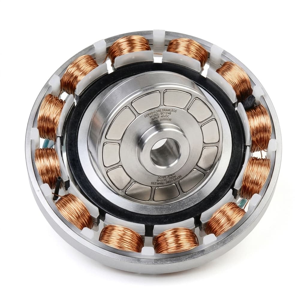
Frameless Servo Motor Rotor Mounting: Press Fit, Shrink Fit, or Gluing?
Compare frameless servo motor rotor mounting methods: gluing, press fit, and shrink fit, with torque risks, tolerances, QC checks, and RFQ guidance for OEMs.
When integrating a frameless servo motor into a robotic joint, an automated guided vehicle (AGV), or a high-precision medical device, the buyer takes on a responsibility usually handled by the motor manufacturer: mounting the rotor to the shaft. Because frameless motors are supplied as separate rotor and stator components without a housing, bearings, or shaft, the mechanical integration determines the ultimate performance, reliability, and lifespan of the direct-drive system.
The decision of how to secure the rotor to the driven shaft—often narrowed down to adhesive bonding (gluing), press fitting, or shrink fitting—is not merely an assembly detail. It is a fundamental engineering and procurement decision. The chosen mounting method dictates the required machining tolerances of the shaft, the tooling required on the assembly line, the maximum continuous and peak torque the joint can transmit, and the total cost of ownership (TCO) when factoring in potential field repairs.
In this comprehensive guide, we will analyze the three primary methods for frameless servo motor rotor mounting. We will explore the mechanical principles, outline the advantages and limitations, provide a detailed comparison matrix, and offer an actionable quality control checklist to ensure your direct-drive systems perform flawlessly under load.
Scope, Assumptions, and Limits
This 2026-07-21 revision is written for OEM engineering, sourcing, and quality teams specifying rotor-to-shaft retention for permanent-magnet frameless servo motor kits. It covers adhesive bonding, press fitting, and shrink fitting for Global industrial applications such as robotics joints, AGVs, precision automation, and medical equipment.
The guidance is a decision framework, not a substitute for the motor maker's outline drawing, magnet-grade limits, adhesive technical data sheet, or a project-specific torque and tolerance calculation. Treat all clearance, runout, curing, and temperature values below as starting checkpoints that must be confirmed against the selected motor frame, shaft material, surface finish, duty cycle, and validation test plan.
The Core Challenge: Why Rotor Mounting Matters
Unlike housed servo motors, where the internal components are factory-sealed and factory-aligned, frameless servo motors require the OEM or systems integrator to establish the critical interface between the permanent magnet rotor and the load-bearing shaft.
This interface must accomplish three absolute mandates:
- Torque Transmission: The connection must handle both the continuous torque and the high instantaneous peak torque of the motor without slipping. A micro-slip between the rotor and shaft can destroy encoder calibration, leading to catastrophic commutation failure and servo runaway.
- Concentricity Maintenance: The rotor must remain perfectly concentric within the stator. The air gap in modern high-torque-density frameless motors is incredibly small (often between 0.4 mm and 0.8 mm). Any eccentricity introduced during mounting will cause cogging torque spikes, uneven magnetic pull (radial forces), and premature bearing wear.
- Thermal Stability: The mounting method must remain stable across the entire operating temperature range of the motor (often -20°C to +120°C or higher). Furthermore, the assembly process itself must not expose the rotor to temperatures that could permanently demagnetize the rare-earth neodymium magnets.
Failure to meet these mandates results in scrapped parts, delayed production, and expensive field failures. Therefore, engineering and procurement teams must align early on the chosen method to ensure the supply chain can deliver shafts with the correct tolerances and surface finishes.
Method 1: Adhesive Bonding (Gluing / Retaining Compounds)
Adhesive bonding, specifically using high-strength anaerobic retaining compounds, is arguably the most common and versatile method for mounting frameless rotors, particularly for small to medium frame sizes and production runs.
How It Works
Instead of relying on mechanical interference, bonding relies on a chemical adhesive to fill the microscopic voids between the rotor inner diameter (ID) and the shaft outer diameter (OD). The adhesive cures in the absence of air and contact with active metals, forming a tough, solid plastic that keys into the surface roughness of both parts. This creates a uniform load distribution across the entire bonded surface area.
Loctite 648 vs Loctite 638: Understanding the Difference
When engineers specify "gluing," they are almost always referring to anaerobic retaining compounds. Two of the industry standards are Loctite 648 and Loctite 638 (or equivalent products from other chemical manufacturers). Understanding the difference is crucial for shaft tolerancing:
- Loctite 648 (Low Viscosity): Designed for tight clearance fits or transitional fits. It has a low viscosity, allowing it to wick into very narrow gaps. The maximum diametrical gap fill is typically around 0.15 mm. This requires the procurement team to source tightly toleranced shafts.
- Loctite 638 (High Viscosity): Designed for larger gaps where parts might be worn or where manufacturing tolerances are looser to save cost. The maximum gap fill is approximately 0.25 mm. While it allows for cheaper shaft manufacturing, the larger gap can make achieving perfect concentricity more challenging during the curing process.
Advantages of Adhesive Bonding
- Zero Stress on Rotor: Because it utilizes a clearance fit (the shaft is slightly smaller than the rotor ID), there are no outward radial forces applied to the rotor core during assembly. This eliminates the risk of fracturing the rotor's magnetic yoke.
- Cost-Effective Machining: While precision is still required for concentricity, the tolerances for a bonded joint are generally more forgiving than those required for a heavy interference press fit.
- Uniform Stress Distribution: The cured adhesive distributes the torque load evenly across the entire surface area, preventing stress concentrations that can occur with keys or splines.
- Sealing Properties: The adhesive prevents moisture and corrosive agents from entering the joint, eliminating fretting corrosion.
Disadvantages and Limitations
- Cure Time: Production lines must accommodate curing times. While handling strength might be achieved in 10 to 30 minutes, full functional cure often takes 24 hours.
- Disassembly is Difficult: High-strength retaining compounds typically require localized heating (often above 250°C) to break the bond. For a frameless rotor, this temperature will irreversibly destroy the neodymium magnets. Therefore, a bonded rotor is generally considered a permanent, non-serviceable assembly. If a motor fails, the entire rotor-shaft assembly may need to be replaced.
- Cleanliness is Critical: The surfaces must be absolutely free of oil, grease, and cutting fluids, requiring strict chemical cleaning protocols on the assembly line.
Best For:
Medium to high-volume production of robotics, AGVs, and gimbals where disassembly is not required, and where avoiding mechanical stress on the rotor is paramount.
Method 2: Press Fit (Interference Fit)
A press fit relies purely on mechanical friction to transmit torque. The shaft's outer diameter is machined to be microscopically larger than the rotor's inner diameter. The rotor is then forcefully pressed onto the shaft using an arbor press or hydraulic press.
How It Works and the Role of Knurling/Splines
The amount of torque a smooth press fit can transmit depends on the degree of interference, the surface area, and the coefficient of friction. For high-torque applications where a smooth press fit might slip, engineers often introduce mechanical features to the shaft:
- Straight Knurling or Splines: The shaft is machined with longitudinal ridges. When the rotor is pressed on, these hardened ridges bite into the softer inner bore of the rotor (which is typically a laminated steel stack or a solid steel hub), creating a permanent mechanical interlock.
- Tolerance Rings: A corrugated metal ring is inserted between the shaft and the rotor. As the rotor is pressed on, the corrugations compress, providing a calculated radial force and friction.
Advantages of Press Fitting
- Immediate Handling Strength: There is no curing time. Once the rotor is pressed on, the assembly can immediately move to the next station on the production line, maximizing throughput.
- High Peak Torque Capacity: A properly designed interference fit, especially one utilizing splines or knurling, can transmit massive amounts of peak torque without micro-slipping.
- No Chemicals Required: Eliminates the need for degreasers, primers, and adhesives, simplifying supply chain management and environmental compliance on the factory floor.
Disadvantages and Limitations
- Risk of Rotor Damage: The interference fit creates significant outward radial stress on the rotor. If the interference is too high, it can distort the rotor, alter the magnetic air gap, or even crack the rotor assembly.
- Strict Machining Tolerances: To achieve the exact required interference without exceeding the rotor's stress limits, the shaft must be machined to exceptionally tight tolerances (often in the low microns). This significantly increases the cost of the mechanical components.
- Specialized Tooling: Assembly requires precision presses and customized guide jigs to ensure the rotor is pressed perfectly straight. Misalignment during pressing can gall the shaft and ruin both components.
- Irreversible: Like bonding, press-fitting (especially with knurling) is generally permanent. Pulling the rotor off often damages the bore, rendering it unusable for reassembly.
Best For:
High-volume automotive and heavy industrial applications where immediate assembly is required, chemical adhesives are prohibited, and the procurement budget allows for ultra-precision shaft machining.
Method 3: Shrink Fit (Thermal Expansion)
A shrink fit is a variation of the interference fit, but instead of using mechanical force to overcome the interference, thermal expansion and contraction are utilized.
How It Works
The concept is simple: heat the outer component so it expands, or cool the inner component so it shrinks, assemble them with zero force, and let them return to room temperature. As temperatures equalize, the components lock together with immense frictional force.
The Danger of Demagnetization: A Critical Warning
When applying shrink fitting to frameless servo motors, there is a massive, critical caveat: You must never heat the rotor.
Frameless rotors contain high-energy rare-earth neodymium magnets (NdFeB). These magnets have a distinct thermal threshold. If they are heated above their maximum operating temperature (often between 120°C and 150°C, depending on the grade), they suffer irreversible demagnetization. The motor will permanently lose torque capacity and efficiency.
Therefore, if a shrink fit is selected, only the shaft can be manipulated. The shaft must be super-cooled (e.g., using liquid nitrogen or dry ice) to shrink its diameter enough to slide easily into the ambient-temperature rotor.
Advantages of Shrink Fitting
- Zero Assembly Force: Because the parts slide together freely, there is no risk of galling the shaft or distorting the rotor during the assembly process.
- Maximum Concentricity: Without the uneven forces of a mechanical press, shrink fitting often yields the best possible concentricity, critical for high-speed or ultra-precision applications.
- Extreme Torque Transmission: Yields a very strong, uniform interference fit capable of handling severe shock loads and high continuous torque.
Disadvantages and Limitations
- Complex Assembly Environment: Handling liquid nitrogen or dry ice on a production floor requires specialized safety equipment, ventilation, and operator training, increasing overhead costs.
- Time Sensitivity: Once the shaft is removed from the cooling medium, the operator has only seconds to position the rotor correctly before the shaft expands and locks in place. If it locks halfway, the assembly is usually ruined.
- Thermal Shock: Extreme cold can alter the metallurgy of certain shaft materials, making them brittle.
Best For:
Aerospace, defense, and specialized high-precision applications where maximum torque density and perfect concentricity justify the cost and complexity of cryogenic assembly processes.
Visualizing the Assembly Interface
To better understand the mechanical realities of these three methods, review the following diagram illustrating the rotor-to-shaft interface.
This diagram illustrates the cross-section of the three primary mounting methods, highlighting the presence of adhesive gaps, mechanical stress, and thermal states.
Comparative Decision Matrix
To assist procurement and engineering in aligning on the best method for your project, use this structured comparison table.
| Feature / Requirement | Adhesive Bonding (Loctite) | Press Fit (Interference) | Shrink Fit (Cryogenic) |
|---|---|---|---|
| Torque Transmission limit | High (Adhesive dependent) | Very High (Requires knurling) | Maximum (Extreme friction) |
| Machining Tolerance Cost | Moderate (Clearance fit) | High (Precision required) | Very High (Precision required) |
| Assembly Cycle Time | Slow (Requires 24h full cure) | Fast (Immediate handling) | Fast (Immediate handling) |
| Rotor Stress / Risk | Minimal (Zero radial force) | High (Risk of deformation) | Minimal (Free slide entry) |
| Field Serviceability | Non-serviceable (Heat destroys magnets) | Generally non-serviceable | Non-serviceable |
| Required Equipment | Applicators, degreasing station | Arbor/Hydraulic Press, jigs | Cryogenic cooling baths, PPE |
Crucial Engineering Considerations
Regardless of which method you select, the following engineering principles must be adhered to during the design phase:
1. Concentricity and the Air Gap
Frameless motors rely on a perfectly uniform air gap between the stator and the rotor. If the rotor is mounted eccentrically (off-center), it will experience unbalanced magnetic pull. This creates massive radial loads on the bearings, drastically reducing their lifespan, and introduces severe cogging torque that ruins smooth motion control. Your shaft runout tolerances must be exceptionally tight, typically in the range of 0.01 mm to 0.02 mm relative to the bearing journals.
2. Axial Positioning
The magnetic center of the rotor must align precisely with the magnetic center of the stator. If they are axially misaligned, the motor will suffer a reduction in the torque constant (Kt) and will generate unwanted axial thrust loads. Always machine a precise shoulder or use a circlip on the shaft to provide a definitive hard stop for the rotor during installation.
3. Magnetic Forces During Assembly
As the rotor approaches the stator during final integration (after it is mounted to the shaft), the magnetic attraction is violent and instantaneous. The rotor will attempt to crash into the inner wall of the stator. Tooling must be designed to securely hold the rotor/shaft assembly and guide it concentrically into the stator with controlled force. Never attempt to hand-insert a large frameless rotor into a stator.
Procurement Impact: How Mounting Method Affects the Supply Chain
For buyers and supply chain managers, the choice of rotor mounting dictates several critical cost drivers:
- Shaft Cost: Adhesive bonding allows for slightly wider tolerances, lowering the unit cost of the machined shaft. Press fitting demands grinding operations that drive up cost.
- Consumables vs. CapEx: Bonding requires ongoing procurement of chemicals with strict expiration dates and storage conditions. Press and shrink fitting require higher initial Capital Expenditure (CapEx) for presses and cryogenic handling equipment, but lower ongoing consumable costs.
- Scrap Rate Risk: A poorly executed press fit can ruin both the expensive frameless rotor and the precision shaft. Bonding offers a slight window for adjustment before curing, but if it cures misaligned, the scrap cost is identical.
Step-by-Step Quality Control Checklist
Use this checklist during pilot production to verify your rotor mounting process:
- Surface Preparation Verification: Are the shaft and rotor bore chemically cleaned and completely free of oil, grease, or rust inhibitors prior to assembly?
- Tolerance Verification: Has the incoming batch of shafts been measured to ensure they fall within the specific tolerance band required for your chosen method (e.g., maximum 0.15mm gap for Loctite 648)?
- Axial Alignment Check: Does the shaft feature a hard shoulder to ensure the rotor seats at the exact required axial position relative to the bearings?
- Thermal Protocol (Shrink Fit Only): Is there a strict protocol explicitly forbidding the heating of the rotor assembly to prevent magnet degradation?
- Runout Measurement: After assembly (and curing, if bonded), is the rotor outer diameter runout measured using a dial indicator to confirm it is within specified limits (< 0.02 mm)?
- Handling Procedures: Are operators using non-magnetic tools and maintaining safe distances from ferromagnetic debris after the rotor is removed from its protective packaging?
Frequently Asked Questions (FAQ)
Q: Can I use heat to remove a bonded frameless rotor for maintenance? A: No. High-strength retaining compounds require temperatures around 250°C to soften. Heating a frameless rotor to this temperature will irreversibly demagnetize the neodymium magnets, destroying the motor. Bonded rotors should be considered permanent assemblies.
Q: If my shaft has a keyway, do I still need an interference fit? A: Keys are generally discouraged in high-performance servo applications because they create localized stress concentrations and can introduce backlash during direction reversals. A proper press fit, shrink fit, or full-surface adhesive bond provides uniform torque transmission without backlash.
Q: Does the adhesive gap affect the magnetic performance of the motor? A: No. The adhesive layer is strictly between the rotor's inner steel hub/bore and your shaft. It does not exist in the air gap between the outer magnets and the stator, so it has no impact on magnetic flux or motor performance.
Q: How do I choose between Loctite 638 and 648 for my motor? A: Consult the manufacturer's technical data sheets. Generally, if your shaft machining is highly precise (gap < 0.15mm), 648 is preferred due to its lower viscosity and ability to penetrate tight clearances. If your tolerances are looser (gap up to 0.25mm), the higher viscosity of 638 is required to fill the gap effectively.
Sources and References
To ensure the highest reliability in your direct-drive systems, we recommend consulting the primary technical literature from adhesive and motor manufacturers:
- Henkel Adhesives: Loctite 648 product data - Low-viscosity, high-strength retaining compound reference for tight cylindrical fits; checked 2026-07-21.
- Henkel Adhesives: Loctite 638 product data - High-strength retaining compound reference for larger narrow bond gaps up to 0.25 mm; checked 2026-07-21.
- MACCON: Storage, Handling, Installation & Assembly Guide for frameless motors - Motor-component handling, alignment, and assembly guidance for frameless motors; checked 2026-07-21.
- Kollmorgen: Mounting, Design, and Installation of Frameless Motors - Rotor-to-shaft bonding, clamping, shaft design, axial positioning, and concentricity guidance; checked 2026-07-21.
Ready to Integrate Frameless Motors into Your Design?
Selecting the right rotor mounting method is just the first step in successful direct-drive integration. Ensuring you have the right motor with the optimal torque density, thermal characteristics, and form factor is equally critical.
If you are designing a new joint for robotics, AGVs, or precision automation, our engineering team is ready to assist with sizing, selection, and integration advice.
Review our complete range of high-performance components in our Products Catalog, or reach out directly with your load requirements via our Contact / RFQ page for a detailed technical review of your application.
Author

Categories
More Posts
Back-EMF Testing for Frameless Motors: Why It Matters in Supplier Quality Control
A practical guide for OEM buyers on using Back-EMF waveform, phase difference, THD, resistance, and insulation checks to qualify frameless motor suppliers.
How to Address Cogging Torque in Frameless Servo Motors: Slotted vs. Slotless Designs
A comprehensive engineering and procurement guide to evaluating cogging torque in direct-drive frameless servo motors. Compare slotted and slotless designs for precision applications.
Frameless Servo Motor Winding Customization: Optimizing KV Rating and Phase Resistance
Learn when to request frameless servo motor winding customization, how KV rating changes phase resistance, and what to send suppliers for RFQ review.