
Frameless Servo Motor Rotor Magnet Retaining Sleeves: Carbon Fiber (CFRP) vs. Inconel 718, Titanium, and Glass Fiber Banding
Specify frameless servo motor rotor magnet retaining sleeves: compare carbon fiber CFRP, Inconel 718, titanium, and glass fiber with tip speed and RFQ checks.
Choose frameless servo motor rotor magnet retaining sleeves by checking centrifugal loading, usable magnetic air gap, total rotor losses, and contact pressure across speed and temperature. CFRP is a candidate when low rotating mass and a thin containment wall matter; Inconel 718 or titanium can suit a qualified metal sleeve design; glass fiber banding can suit an electrically insulating winding process. None is the best choice for every rotor.
A frameless motor kit delivers an unhoused stator and rotor for integration into the customer's machine. This guide addresses inner-rotor, surface-mounted permanent-magnet (SPM) assemblies, with magnets on the hub outside diameter. Outer-rotor and interior-magnet machines require different load paths. A failed magnet bond or retention system can damage the rotor and stator and must be addressed in the assembly's mechanical qualification.
Published and reviewed: 2026-11-08. Scope: Global OEM engineering and procurement teams specifying frameless servo kits. This is a preliminary selection and RFQ framework, not a certified sleeve design or an in-house test report. Calculated examples use stated assumptions; material properties, sleeve thickness, interference, and acceptance limits require supplier data and application validation. High-speed motor-generator research supplies relevant mechanisms, but its ratings do not transfer directly to robot joints or other frameless servo assemblies.
For a new rotor or a changed speed, temperature, or drive waveform, request a rotor retention review with the rotor diameter, maximum operating speed, temperature range, and available radial envelope.
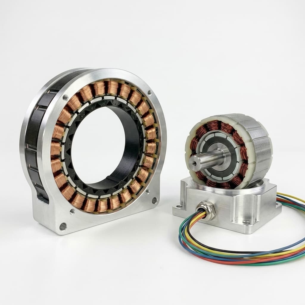
Illustrative motor assemblies. This image does not identify a sleeve material or demonstrate a qualified retention design; the cross-section below explains the inner-rotor geometry discussed here.
1. Mechanical Physics: Adhesive Loads and When to Evaluate a Sleeve
In surface permanent magnet (SPM) frameless motors, rare-earth neodymium (NdFeB) or samarium-cobalt (SmCo) magnet segments are glued directly onto the outer cylindrical diameter of the soft magnetic rotor hub. During rotation, each magnet segment is subjected to outward centrifugal force:
Fc = m · ω² · r = m · (v_c² / r)
Where m is magnet mass in kg, ω is angular velocity in rad/s, and r is the radius to the magnet's center of mass in m. In the equivalent expression Fc = m · v_c² / r, use the center-of-mass speed v_c = ωr. Surface tip speed is a different screening quantity:
v_tip = (π · D_rotor · n) / 60
Here D_rotor is the specified outside diameter in m and n is RPM. State whether the diameter refers to the magnets or the finished sleeve. A 60 mm diameter at 8,000 RPM gives v_tip = 25.1 m/s; this arithmetic alone does not establish adhesive adequacy or an allowable operating speed.
Adhesive Qualification and the Retention Decision
Adhesive-only retention needs a demonstrated load path and test evidence for the actual magnet coating, hub surface, bond thickness, cure, and temperature cycle. A room-temperature shear result is not an allowable radial peel stress for a segmented magnet. A sleeve can provide mechanical containment, but it also introduces hoop stress, assembly damage risks, and an air-gap allocation.
Two mechanisms deserve particular attention:
- Temperature-dependent adhesive behavior: stiffness, strength, and creep resistance depend on formulation and cure. Glass transition temperature is relevant but is not by itself the adhesive's service-temperature limit. Use hot-strength and aging data rather than a generic percentage strength reduction.
- Differential expansion and cycling: the hub, magnet, coating, and adhesive expand differently. NdFeB expansion is directional; the effective radial behavior of the assembled hub and magnets cannot be inferred from a single coefficient. Acceleration adds tangential loads while rotation creates radial loads.
For example, Henkel's LOCTITE 648 technical data sheet identifies an anaerobic urethane-methacrylate retaining compound, not a two-part epoxy. Its pin-and-collar results describe particular substrates and cure conditions. They do not qualify a rotor magnet bond.
There is no universal 30, 40, or 50 m/s threshold that proves adhesive-only retention safe or makes a particular sleeve mandatory. Determine retention requirements from the assembled rotor's loads, temperature, fatigue duty, failure consequences, and qualification evidence.
2. Retaining Sleeve Material Benchmark: CFRP vs. Inconel 718, Titanium, Stainless Steel, and Glass Fiber
Engineering teams must choose between high-modulus composite sleeves, non-magnetic metallic superalloys, or wet-wound fiber prepregs. Each material family involves fundamental trade-offs between mechanical burst margin, electrical eddy current losses, radial thermal conductivity, and manufacturing cost.
Comprehensive Material Comparison
The six-row comparison below supports shortlisting. It deliberately separates adhesive bond performance from sleeve hoop strength: those values are different failure modes and cannot be ranked as equivalent tensile ratings. No row supplies a certified allowable stress or a production price.
| Retention option | Principal advantage | Mechanical qualification | Electrical behavior | Thermal and assembly limitation | RFQ evidence to request |
|---|---|---|---|---|---|
| Bare bonded baseline | Small radial envelope and no added containment mass | Validate bond shear, peel, fatigue, and aging on actual substrates | No conductive sleeve; magnet losses remain | Cure, surface condition, and hot-strength sensitivity | Adhesive identity, coating compatibility, cure records, bond tests |
| CFRP sleeve | Low mass and high hoop-specific strength with suitable layup | Use cured-laminate directional allowables, winding tension, and defect limits | Conductive and anisotropic; sleeve loss can be lower than metal, but is not automatically zero | Through-thickness heat transfer and matrix aging can limit the design | Fiber/resin grade, layup, cure, hot/wet properties, inspection method |
| Inconel 718 sleeve | Strong metal containment with specified heat treatment | Verify yield, fatigue, thickness, and interference for the supplied condition | Conductive; harmonic shielding also produces sleeve losses | Adds rotating mass; forming and finishing affect tolerances | Material certificate, product form, heat treatment, loss calculation |
| Ti-6Al-4V sleeve | Lower mass than a comparable nickel-alloy sleeve | Confirm grade, modulus, fatigue, and radial growth | Conductive; the actual harmonic field determines losses | Thin-wall machining and fit control require process capability | Grade/condition certificate, finished geometry, fit and loss model |
| Austenitic stainless sleeve | Potential sourcing and fabrication simplicity | Grade and cold-work condition determine strength and permeability | Conductive; do not assume a cold-worked part is nonmagnetic | Thickness and mass may consume the available radial envelope | Material condition, permeability if critical, runout and stress evidence |
| Glass fiber banding | Electrically insulating reinforcement | Qualify fiber/resin system, winding tension, and cured hoop stiffness | Reinforcement is insulating; conductive coatings or other rotor parts still dissipate heat | Required wall and cure depend on the assembly | Winding process, resin temperature limit, wall tolerance, sample validation |
In-Depth Material Breakdown
1. Carbon Fiber Reinforced Polymer (CFRP)
A wound CFRP sleeve can put most reinforcement in the hoop direction, where containment demands it. Low density reduces the sleeve's own centrifugal loading, but that loading is not negligible by definition. The fibers also carry loads transferred from the magnets. A fiber supplier's tensile strength is not the cured sleeve's allowable hoop stress.
Limitations: Specify the laminate rather than simply ordering “carbon fiber.” Fiber volume, winding angle, resin, cure, voids, and temperature affect performance. Hoop stiffness does not establish radial strength or through-thickness thermal conductivity. Check both insufficient contact pressure and excessive compression throughout the operating envelope.
2. Inconel 718 Superalloy
Inconel 718 is an age-hardenable nickel alloy used where metal strength and temperature capability are useful. The Special Metals alloy 718 bulletin provides condition-dependent physical and mechanical data. Its typical properties are reference information, not a sleeve specification or acceptance certificate.
Limitations: A metal sleeve adds rotating mass and can generate harmonic eddy-current heat. It can also shield the magnets from some harmonics. Compare the resulting sleeve, magnet, and hub losses together rather than selecting on sleeve loss alone. Request the supplied heat treatment and product form before using a yield value in a calculation.
3. Titanium Grade 5 (Ti-6Al-4V)
Titanium can reduce rotating mass relative to a nickel-alloy alternative. Its lower stiffness can increase radial growth for the same geometry and loading, so replacing one material with another at equal wall thickness is not a qualified substitution.
Limitations: Compare actual fit, wall tolerance, fatigue, and harmonic losses. A lower conductivity does not guarantee a fixed percentage reduction in total rotor heat. Magnet anisotropy and hub expansion also prevent a blanket claim that titanium always matches the rotor's thermal expansion.
4. Glass Fiber Prepreg Banding (E-Glass / S-Glass)
Glass fiber reinforcement provides an insulating containment option. Direct winding can suit a rotor that permits the required wall, cure, and dimensional control. It is worth comparing against a precured sleeve when tooling, batch size, and assembly access matter.
Limitations: Do not prescribe a universal 1.5–2.5 mm wall or rule glass banding out solely by application name. Determine the wall from the qualified winding system and loads, then check the electromagnetic envelope. For procurement, compare finished assembly yield, inspection, tooling amortization, and replacement cost at the same quantity and acceptance criteria.
3. Electromagnetic Trade-Offs: Air Gap Expansion and Eddy Current Losses
Installing a retaining sleeve fundamentally alters the electromagnetic circuit of a frameless servo motor. The sleeve must fit physically into the gap between the stator lamination inner diameter (ID) and the magnet outer diameter (OD).
Layer schematic, not a dimensional drawing. The orange film represents an optional outer bondline. A hub-to-magnet bondline and other reluctances need separate treatment in the actual magnetic model.
1. The Magnetic Air Gap Penalty
For a nonmagnetic sleeve, a simple gap allowance is:
g_eff = g_mech + t_sleeve + t_glue
Here g_mech is the running clearance outside the finished rotor, and t_glue is an outer nonmagnetic bond-film allowance if present. These dimensions must fit inside the stator bore. Adding a sleeve to an unchanged rotor consumes running clearance; preserving that clearance requires a geometry change. It is not a drop-in modification.
Reproducible screening example, not measured motor performance: hold running clearance at 0.60 mm and a nonmagnetic outer film allowance at 0.05 mm. A bare comparison has g_bare = 0.65 mm. Adding a 0.50 mm sleeve gives g_eff = 1.15 mm, an increase of 76.9% in this gap allowance, not in the reluctance of the entire magnetic circuit.
For a one-dimensional magnetic circuit with a 3.0 mm magnet, assume magnet recoil relative permeability of 1, equal areas, and negligible leakage, saturation, slotting, and end effects. Then:
Bg_sleeved / Bg_bare ≈ (lm + g_bare) / (lm + g_eff)
= (3.0 + 0.65) / (3.0 + 1.15) = 0.8795
The estimated flux reduction is 12.0%. If torque constant tracks flux and winding resistance is unchanged, equal torque needs 1 / 0.8795 = 1.137 times the current and 1.137² = 1.293 times the copper loss, or 29.3% more. This illustrates sensitivity; it does not predict a particular motor's rating. Recalculate with the actual recoil permeability, geometry, drive limits, and electromagnetic model.
2. Eddy Current Losses in Metallic Sleeves
Sleeve heating is driven by time-varying flux in the rotor frame, including slotting, winding-space harmonics, and drive-current harmonics. The synchronous fundamental is ideally stationary relative to the rotor. The stator electrical fundamental frequency alone is therefore not a sleeve-loss frequency.
A general thin-lamination formula cannot predict cylindrical sleeve watts without the field direction, current path, axial length, end effects, and harmonic spectrum. Conductivity, thickness, skin effect, and shielding interact. For calculations in SI units, convert conductivity from MS/m to S/m by multiplying by one million.
Request a loss model using the actual stator and measured or specified phase-current waveform. Compare total sleeve, magnet, and hub losses, followed by the resulting temperatures. CFRP is electrically anisotropic and must not be treated as a perfect insulator. A metallic sleeve may dissipate heat while reducing magnet heating through shielding; neither sleeve material guarantees the lower total rotor loss.
Before freezing the radial stack, send the proposed wall and running-clearance budget for review, including the drive waveform or switching conditions available to your team.
4. Thermal Dissipation & The Composite "Thermal Trap"
Reducing sleeve eddy losses does not automatically reduce magnet temperature. A sleeve also changes the thermal path from the magnets to the air gap, while the hub, shaft, ends, and surrounding stator provide other heat-transfer paths.
The Anisotropy of Filament-Wound Composites
A hoop-wound composite can have very different properties along the fibers and through its thickness. Request the cured laminate's radial thermal conductivity, contact resistance, and temperature dependence. Fiber-axis conductivity is not a substitute for radial conductivity. Compare the complete thermal network rather than assigning every CFRP assembly the same temperature penalty.
For a uniform cylindrical sleeve, a first conduction estimate is R_th = ln(r_outer / r_inner) / (2π · k_r · L), where radii and active length L are in m and k_r is radial conductivity in W/(m·K). This gives thermal resistance in K/W. It assumes steady radial conduction and excludes interface resistance, axial heat paths, and air-gap convection. Those omissions need explicit treatment before estimating magnet temperature.
Temperature, Torque Drift, and Irreversible Demagnetization
Magnet remanence normally changes reversibly with temperature within its qualified operating region. A reversible hot-state reduction in torque constant is not permanent demagnetization. Irreversible loss depends on the grade's temperature-dependent demagnetization curves, magnetic load line, and opposing field, including fault conditions.
Do not approve a sleeve using a magnet's nominal temperature label alone. Request the magnet grade and coating, minimum coercivity data at relevant temperatures, predicted hot-spot temperature, and worst-case armature field. Validate steady running, overload, cooling loss, and thermal cycling. A cooler stator does not by itself prove a cooler or demagnetization-safe rotor.
5. Manufacturing & Assembly: Interference Fits, Lamé Equations, and Pre-Stress
A preloaded retention design must maintain the required contact while keeping sleeve stress and magnet compression within qualified limits. The drawing below illustrates contact-pressure trends only. It contains no measured pressures, material ranking, or certified burst margin. Actual pressure can vary differently with geometry and temperature.
Contact Pressure, Cylinder Models, and Pre-Stress
A useful bookkeeping expression is:
P(n, T) = P_assembly + ΔP_rotation(n, T) + ΔP_thermal(T)
The increments are signed, model-derived changes, not fixed material constants. Check the magnet-to-hub and magnet-to-sleeve interfaces separately: outer contact does not prove adequate hub contact. Loss of required interface pressure is one failure criterion; excessive sleeve stress, magnet cracking, fatigue, or unstable rotor dynamics can govern first.
Isotropic thick-cylinder models can support preliminary metal-sleeve analysis when their assumptions apply. A wound composite needs directional stiffness and thermal-expansion properties. A segmented magnet assembly with adhesive, a hollow hub, and axial end effects may require a coupled contact model. A single isotropic Lamé equation is not an adequate composite design certificate.
Set interference from the complete assembly stiffness, tolerance extremes, temperature distribution, and speed range. Check cold start, hot running, transients, and specified proof conditions. A metal sleeve that expands more than its core can loosen; a hotter core may instead increase interference. A low hoop-expansion CFRP sleeve can develop excessive compression. Neither material fixes the direction or magnitude of contact-pressure change in every rotor.
Assembly Methods in Factory Production
- Qualified press or assisted fit: Define the lead-in, surface protection, allowable force/displacement trace, and inspection after assembly. Prevent damage to coatings, magnet edges, and structural fibers. Cooling a core is an engineered process with thermal-shock and condensation controls, not a generic instruction to immerse magnets in liquid nitrogen.
- Controlled thermal shrink fit for metal sleeves: Select sleeve temperature and dwell from the required expansion and every component's allowable exposure. Do not prescribe a blanket 300–400°C process or a quench for an adhesive-bonded magnet assembly. Record the thermal cycle and inspect the final fit.
- Direct composite winding: Qualify winding tension, layup, consolidation, and cure against the magnet, coating, and adhesive limits. Direct winding does not guarantee zero voids or complete contact. Agree any finish allowance and verify the final wall, runout, and defect criteria.
6. Dynamic Balancing, Overspeed Testing, and Quality Verification
Because a frameless rotor is mounted on the customer's shaft or hub, component acceptance must relate to the finished rotating assembly. A balanced loose rotor does not establish the machine's final vibration behavior.
Dynamic Balance and Runout Acceptance
Specify the service speed, datum axis, permitted residual unbalance, correction planes, and approved correction zones. Choose single- or two-plane balancing from rotor geometry and dynamic behavior rather than automatically requiring two planes for every sleeve. The agreed balance grade and method belong on the drawing or acceptance plan.
Do not remove structural hoop fibers or drill magnets to correct balance. Any permitted end-ring correction must preserve strength, clearances, and traceability. Measure sleeve runout relative to the mounting datum and include shaft, bearing, fit, thermal growth, and dynamic deflection in the running-clearance budget.
Overspeed Spin Testing Protocols
Agree proof speed, dwell, temperature, containment, sample rate, and inspection with the responsible design authority. A statement such as “120% for three minutes” is only a proposed test condition until approved for the product and application. It is not a universal rotor standard or evidence of a burst safety factor.
Define what establishes acceptance: dimensional stability, balance retention, absence of cracks or delamination, and the agreed functional checks. Set numerical limits from the design and measurement capability. A proof test does not replace fatigue analysis, material allowables, or a thermal qualification plan.
Non-Destructive Testing (NDT)
For composite sleeves, request an inspection method demonstrated on the actual thickness and geometry, with detectable defect sizes and rejection criteria. Ultrasound can be useful, but curvature, interfaces, and thin sections affect interpretation. For metal sleeves, choose suitable surface or electromagnetic inspection with qualified procedures. A sealed can additionally needs a leak-rate requirement derived from the intended environment. No universal void-area or leak-rate limit applies to every frameless rotor.
7. Application Boundary Matrix & Sourcing Checklist
Use the matrix to decide what to investigate and what evidence to request. It is not a safe-speed chart. Peripheral speed screens loading, but diameter, magnet mass, hub stiffness, temperature, fatigue, and failure consequences determine the approved design.
Application Boundary and Supplier Evidence Matrix
| Application condition | Retention candidates to evaluate | Main engineering question | Evidence needed before approval |
|---|---|---|---|
| Low-speed direct drive | Qualified adhesive-only design or mechanically retained assembly | Does the bond withstand radial, acceleration, and thermal-cycle loads? | Actual-substrate bond qualification and service envelope |
| Frequent reversing or high acceleration | Bonded design with justified containment where needed | Are tangential fatigue and coating adhesion limiting? | Duty cycle, peak acceleration, fatigue and thermal-cycle evidence |
| High peripheral speed | CFRP, metal, or qualified glass banding | Does contact remain acceptable without exceeding sleeve or magnet limits? | Coupled stress/contact model and approved spin-test record |
| Tight magnetic gap | Thin qualified sleeve with coordinated motor geometry | Can the finished rotor retain running clearance and required torque? | Tolerance stack, electromagnetic calculation, torque-current validation |
| High harmonic content | Metal, composite, or combined shielding design | Where are sleeve, magnet, and hub losses generated? | Actual-drive loss model and temperature validation |
| Limited rotor cooling | Sleeve selected with the whole heat path | Can heat leave the magnets during continuous duty and overload? | Radial/axial thermal model and hot-spot validation |
| Vacuum, moisture, or chemicals | Compatible coatings, enclosure, or engineered sealed can | Does the whole barrier meet permeability, outgassing, and corrosion requirements? | Environment-specific material, sealing, and leakage evidence |
OEM Engineering & RFQ Specification Checklist
Before issuing a Request for Quotation (RFQ), align the technical drawing and acceptance plan:
- Operating envelope: State continuous and transient RPM, acceleration, duty cycle, temperature limits, and separately approved proof-test conditions.
- Geometry and tip speed: Identify magnet OD, finished sleeve OD, active length, hub bore, and mounting datum. State the diameter used for
v_tip. - Sleeve specification: Name metal grade, product form, and heat treatment, or the composite fiber/resin system, layup, and cured-property basis.
- Radial allocation: Budget running clearance, sleeve wall, any outer bond film, tolerances, thermal growth, and dynamic deflection. Avoid copying a generic minimum gap.
- Contact and stress model: Check tolerance extremes and cold/hot speed cases against qualified limits for the sleeve, magnets, coating, and adhesive.
- Runout and balance: Define datum, measurement setup, acceptance limits, correction planes, and permitted correction zones.
- Electrical and thermal evidence: Include drive conditions, total rotor-loss estimate, cooling assumptions, and demagnetization assessment.
- Quality and commercial basis: Require traceable material/cure records, agreed NDT and spin-test sampling, tooling ownership, minimum order quantity, lead time, and a clear replacement policy.
Compare quotations at the same finished geometry, validation scope, and annual quantity. A lower raw-material price can be outweighed by a wider air gap, scrap, inspection cost, or a difficult repair path. Resolve who owns rotor design approval and final machine qualification before releasing production drawings.
8. Frequently Asked Questions (FAQ)
Can a carbon fiber retaining sleeve be machined after it is pressed onto the rotor?
Only when the qualified design includes a defined finish allowance and process. Removing hoop fibers changes containment capacity; there is no universal safe 0.05 mm skim. Agree tooling, dust extraction, temperature control, coolant compatibility if used, final wall measurement, and reinspection with the sleeve supplier.
Why not use austenitic stainless steel for all metallic sleeves?
Strength, conductivity, mass, permeability, and final wall thickness depend on grade and processing condition. Stainless can be practical in a suitable design, but a thicker wall may consume the available magnetic gap. Compare certified properties and total rotor losses rather than prescribing a material from RPM alone.
How does magnet chamfering affect sleeve installation?
A qualified lead-in and controlled edge condition can reduce coating damage, sleeve gouging, and local stress. Define chamfer or radius dimensions on the assembly drawing from magnet geometry and the installation method. A generic corner size can remove useful magnetic material or still fail to protect the sleeve.
Does a carbon fiber sleeve protect magnets from moisture or chemical corrosion?
Do not treat a standard composite sleeve as a hermetic barrier. Resin, interfaces, end sealing, and environmental exposure determine protection. Select compatible magnet coatings and enclosure features, and validate the complete barrier. A metal can also needs qualified joints and sealing to provide hermetic protection.
What is the maximum operating temperature limit for a CFRP sleeved rotor?
The limit is assembly-specific. Matrix aging, hot/wet laminate allowables, magnet demagnetization behavior, adhesive, coating, and fit can each govern. Request continuous and transient ratings with exposure duration and validation evidence; fiber temperature capability or resin glass transition temperature alone does not rate the rotor.
How does sleeve thickness influence motor torque constant (Kt)?
If running clearance is preserved by changing the geometry, a thicker nonmagnetic sleeve generally adds magnetic gap and can reduce flux and torque constant. The worked example in Section 3 shows the assumptions behind one estimate. No fixed percentage loss per 0.1 mm applies across different magnet thicknesses, saturation levels, and rotor geometries.
Can broken or detached magnets be repaired if a sleeved rotor fails?
Stop using the damaged rotor and seek a supplier disposition. Sleeve removal and magnet replacement can alter the hub, bond, fit, balance, and containment. Field repair is not an approved default; any supplier-approved rebuild needs defined inspection and requalification. Include replacement and service terms in the original RFQ.
9. Authoritative Sources & Engineering References
The three primary sources below support mechanisms or product-specific information, not universal safe speeds or a certified servo design. Reviewed for this article on 2026-11-08.
- Calnetix Technologies — Rotor Retention and Loss Reduction for High-Speed Permanent Magnet Motor Generators, A. T. Andonian and Co Huynh. Pages 1–5 discuss retention, pre-stress, and assembly methods; pages 7–8 discuss harmonic shielding and rotor heat paths. Its high-speed motor-generator examples are not validation data for the frameless servo kits pictured here.
- Special Metals — INCONEL alloy 718 technical bulletin SMC-045, September 2007, especially pages 1–3. Supports condition-dependent alloy properties and the distinction between typical reference data and procurement specifications.
- Henkel — LOCTITE 648 Technical Data Sheet, May 2021, pages 1–3. Supports adhesive chemistry, cure dependence, and product-specific test conditions. These cylindrical-joint tests do not establish a magnet-retention allowable.
The gap and thermal-resistance calculations are transparent screening methods supplied in this article. No in-house dynamometer results, measured comparative sleeve losses, or customer qualification records are claimed.
10. Summary & Next Steps for OEM Engineering Teams
Specifying rotor magnet retention requires a coordinated mechanical, electromagnetic, thermal, and production decision:
- Start with the operating envelope and radial stack. Establish whether the existing rotor is already qualified for the application before adding a sleeve that consumes clearance.
- Shortlist materials using assembly evidence. CFRP, Inconel 718, titanium, stainless, and glass fiber each have useful roles; a material name or tip-speed band does not confer an allowable rating.
- Release against agreed acceptance criteria. Require traceable properties, a coupled fit/stress assessment, actual-drive loss and temperature checks, and a documented inspection and qualification plan.
To discuss your rotor geometry, validation requirements, and available sleeve options, contact our engineering team with the RFQ checklist above, or explore our frameless servo motor kits before defining the integration envelope.
Author

More Posts
Frameless Motor Magnet Grades: NdFeB SH/UH/EH Guide
Procure frameless servo motor magnet grades with a practical SH, UH, and EH selection framework, thermal margins, evidence requests, and RFQ checks.
Frameless Servo Motor Commutation Alignment: Establishing Electrical Zero in High-Performance Joint Actuators
Frameless servo motor commutation alignment: compare electrical-zero methods, avoid encoder errors, and prepare an RFQ checklist for your integration review.
Frameless Servo Motor Stator Potting: A Buyer's Guide to Thermal Management and Torque Density
Learn how stator potting and encapsulation improve thermal dissipation, allowing frameless servo motors to achieve higher continuous torque density in robotics.