
Position Feedback for Frameless Motors: Magnetic vs. Optical Encoders vs. Resolvers
Compare resolver, optical encoder, and magnetic encoder choices for frameless servo motors. Use the engineering checklist before RFQ or drive selection.
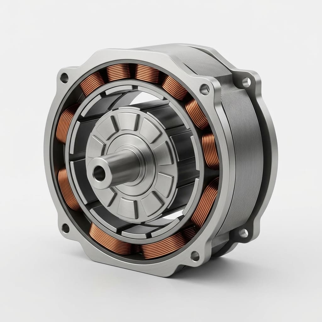
When an Original Equipment Manufacturer (OEM) decides to use a frameless servo motor, they are taking on a specific design responsibility: the motor comes as a bare rotor and stator. There is no housing, there are no bearings, and crucially, there is no built-in feedback device.
For engineers and procurement teams, this means the responsibility of selecting, mounting, and qualifying the position feedback sensor shifts entirely to the buyer's side of the table. The choice between a resolver, an optical encoder, and a magnetic encoder will dictate not just the precision of your motion control system, but also its environmental durability, its total cost of ownership, and the complexity of your servo drive architecture.
This guide is current as of July 25, 2026 and is written for global OEM engineering, sourcing, and procurement teams selecting feedback before RFQ release, prototype freeze, or servo-drive nomination. Use it with our torque-speed curve interpretation guide, frameless motor thermal design guide, and evidence-based RFQ procurement checklist. It does not replace supplier encoder datasheets, resolver temperature ratings, servo-drive compatibility tests, magnetic flux leakage FEA, machine safety review, or final commutation tuning.
If you already know the hollow-bore ID, bus voltage, IP target, startup safety requirement, and preferred feedback protocol, share those constraints through Contact / RFQ before finalizing the feedback bill of materials.
The Core Dilemma: Owning the Feedback Problem
In a standard housed servo motor, the manufacturer has already matched the feedback device to the motor's capabilities. They have aligned the encoder to the magnetic poles (commutation alignment) and sealed the housing to an IP65 or IP67 rating, protecting the delicate optics or electronics inside.
With a frameless motor, the OEM must integrate the feedback device directly into their machine's mechanical structure—such as a robotic joint, an optical gimbal, or a medical imaging gantry. This introduces several procurement and engineering challenges:
- Mechanical Fit: Frameless motors often feature a large hollow bore (through-hole) to pass cables, lasers, or fluids. The feedback device must usually match this hollow-bore format, leading to the use of "ring encoders" rather than traditional shaft-end encoders.
- Environmental Vulnerability: Because the OEM designs the housing, the effectiveness of the sealing determines whether sensitive optical components will survive dust, oil, or condensation.
- Drive Compatibility: The chosen feedback device dictates the necessary servo drive hardware. A rugged resolver might seem cheap, but it requires specific (and often expensive) analog-to-digital conversion hardware at the drive level.
Let's dive into the three primary technologies available for frameless motor feedback.
1. Resolvers: The Rugged Legacy Standard
How They Work
A resolver is essentially a rotary electrical transformer. It consists of a primary winding (usually on the rotor) and two secondary windings (on the stator) placed 90 electrical degrees apart. As the rotor turns, the magnetic coupling between the primary and secondary windings changes, outputting sine and cosine analog voltages that represent the absolute angle of the shaft within one revolution.
Engineering Advantages
Resolvers are famous for their near-indestructible nature. Because they contain no glass disks, no delicate LEDs, and no complex microelectronics onboard, they can survive environments that would immediately destroy an encoder.
- Temperature Limits: Many resolver families are available with 150°C to 200°C class ratings, matching or exceeding the thermal limits of common frameless motor winding insulation systems.
- Shock and Vibration: They are highly resistant to mechanical shock, making them the default choice for aerospace, defense, and heavy stamping presses.
- Radiation: Resolvers can be designed to withstand ionizing radiation, making them suitable for nuclear environments and space applications.
Procurement and TCO (Total Cost of Ownership) Considerations
From a purchasing perspective, a bare resolver is often inexpensive. However, procurement teams must look at the Total Cost of Ownership. Resolvers output raw analog signals. To use these signals in a modern digital control loop, the servo drive must have a Resolver-to-Digital Converter (RDC). Drives with built-in RDCs are generally more expensive and offer fewer vendor choices than drives designed for standard digital encoders. Furthermore, resolving the analog signal to high precision (e.g., 16-bit or 20-bit equivalent) requires highly shielded cables to prevent electromagnetic interference (EMI) from the nearby motor power cables. The cost of premium shielded cabling can easily offset the savings on the sensor itself.
2. Optical Encoders: The Precision Benchmark
How They Work
An optical encoder uses an LED light source shining through a rotating disk marked with precise opaque and transparent lines. A photodetector on the other side reads the light pulses as the disk turns, converting them into digital square waves (incremental) or a unique digital word (absolute).
Engineering Advantages
When it comes to pure precision, optical encoders are unmatched.
- High Resolution: High-end optical ring encoders can achieve resolutions exceeding 24 bits (over 16 million counts per revolution).
- Zero EMI Susceptibility: The optical sensing mechanism is immune to the intense magnetic fields generated by the frameless motor's rare-earth magnets.
- Low Runout Error: Glass disks can be manufactured with extraordinary geometric precision, reducing cyclic errors in the position signal.
The Vulnerability: Contamination
The fatal flaw of the optical encoder in a frameless motor application is its sensitivity to the environment. If dust, oil mist, or condensation gets between the LED and the photodetector, the encoder will drop counts or fail completely. For OEM engineers, this means the mechanical housing enclosing the frameless motor and the optical encoder must be perfectly sealed. If your application involves machining fluids or heavy dust, and you cannot guarantee IP67 sealing at the system level, optical encoders pose a high warranty risk.
Procurement Perspective
Optical encoders are generally the most expensive feedback option. High-resolution absolute optical ring encoders for large-bore frameless motors can sometimes cost as much as the motor itself. Buyers should carefully question whether the application truly requires sub-arc-second precision (like a satellite tracking gimbal) or if a cheaper alternative would suffice.
3. Magnetic Encoders: The Modern Compromise
How They Work
Magnetic encoders rely on a rotating magnetic scale (often a multipole magnetic ring) and a stationary read-head containing Hall-effect or Magnetoresistive (MR) sensors. As the magnetic poles pass the sensor, it detects the changing flux and converts it into a digital position signal.
Engineering Advantages
Over the last decade, magnetic encoders have advanced rapidly, becoming the default choice for collaborative robots (cobots), AGVs, and general factory automation.
- Robustness: Because they rely on magnetic fields rather than light, properly rated magnetic scales are much more tolerant of dust, dirt, oil mist, and moisture than exposed optical disks.
- Form Factor: Magnetic ring encoders perfectly complement the hollow-bore design of frameless motors. They can be incredibly thin, taking up minimal axial space.
- Resolution: While historically inferior to optical encoders, commercial interpolated magnetic encoder systems can reach 18-bit to 20-bit class resolutions. Exact usable accuracy still depends on scale diameter, read-head alignment, interpolation error, and drive filtering.
The Vulnerability: Stray Magnetic Fields
The primary risk with magnetic encoders is interference from the frameless motor itself. Frameless motors use powerful neodymium magnets. If the magnetic encoder read-head is placed too close to the motor's end-turns or rotor magnets without proper magnetic shielding, the stray flux can distort the encoder's readings. Engineers must carefully design the axial spacing or use mu-metal shielding.
Procurement Perspective
Magnetic encoders offer the best cost-to-performance ratio. They are significantly cheaper than high-end optical ring encoders and provide native digital outputs (unlike resolvers), meaning you can use standard, cost-effective servo drives. For procurement teams sourcing components for mid-volume robotics, magnetic encoders are often the sweet spot.
Visualizing the Architecture
To understand how these sensors physically integrate with a frameless motor, consider the following schematic representation of a typical hollow-bore robotic joint:
In frameless integrations, the magnetic or optical ring is attached to the rotating customer shaft, while the read-head is fixed to the stationary housing. Maintaining the precise concentricity and air gap between the ring and the read-head is one of the most critical mechanical challenges.
Absolute vs. Incremental Protocols
Beyond the sensing physics, procurement must choose the communication protocol.
- Incremental (ABZ): Only tracks changes in position. At startup, the motor does not know its absolute angle. It must perform a "wake-and-shake" or find a physical home switch before it can safely commutate and apply full torque. These are cheaper but add cycle time and safety risks in automation.
- Absolute (BiSS-C, SSI, EnDat): Provides a unique digital word for every position in the 360-degree rotation. The drive knows the exact rotor position the millisecond it powers on. For gravity-loaded, direct-drive, or safety-sensitive frameless robotics, absolute feedback is usually required to prevent unexpected motion at startup.
Comprehensive Comparison Matrix
Use the following table to compare the three technologies across critical decision vectors. Treat the numbers as RFQ screening ranges, not guaranteed limits; final limits must come from the selected feedback supplier's datasheet and your assembled-axis validation.
| Feature Dimension | Resolver | Optical Encoder | Magnetic Encoder |
|---|---|---|---|
| Sensing Principle | Electromagnetic Induction | Light Interruption | Magnetic Flux Detection |
| Environmental Durability | ⭐⭐⭐⭐⭐ (Excellent) | ⭐ (Poor - fails with dust/oil) | ⭐⭐⭐⭐ (Very Good) |
| Resolution Limit | Medium (Drive dependent) | Ultra-High (>24-bit possible) | High (Up to ~20-bit) |
| Shock & Vibration Limit | > 200G | Typically < 50G | ~ 100G |
| Output Type | Analog (Sine/Cosine) | Digital (SSI, BiSS, ABZ) | Digital (SSI, BiSS, ABZ) |
| Drive RDC Required? | Yes (Adds system cost) | No | No |
| Interference Risk | High frequency noise | Airborne contaminants | Motor stray magnetic flux |
| Relative Component Cost | Low | Very High | Medium |
| Typical Application | Aerospace, Metal forming | Optical gimbals, Lithography | Cobots, AGVs, Factory Automation |
The OEM Integration Checklist
If your engineering and procurement teams are preparing to source feedback devices for a frameless servo motor project, run through this checklist before issuing POs:
- Define the Bore Size Requirement: Does your application require a through-hole? If so, what is the minimum inner diameter (ID)? This will restrict you to ring encoders or hollow-shaft resolvers.
- Verify Drive Compatibility: Ask your servo drive supplier exactly which protocols they support natively. Do they require an expensive option card for BiSS-C? Do they have an onboard RDC for resolvers?
- Calculate the Commutation Alignment Plan: Frameless motors require you to align the encoder's zero position to the motor's electrical zero phase (Phase U). Have your engineers documented how this alignment will be performed on the assembly line?
- Assess the Operating Environment: Will the motor housing be IP67 sealed? If you cannot guarantee a dust-free and oil-free cavity, immediately disqualify optical encoders.
- Check Stray Magnetic Fields: If choosing a magnetic encoder, request the frameless motor manufacturer to provide a magnetic flux leakage simulation (FEA) to ensure the motor magnets won't saturate the encoder read-head.
- Evaluate Cable Routing: High-resolution encoders require highly shielded cables. Ensure your mechanical design has enough space for proper cable bend radii without pinching the shielding.
Frequently Asked Questions (FAQ)
1. Can I run a frameless motor without any feedback device?
Yes, using a technique called "Sensorless Field Oriented Control" (Sensorless FOC). However, sensorless control struggles at zero speed and very low speeds. For position control, robotics, or holding a load against gravity, a physical feedback device is mandatory.
2. What is "Commutation Alignment" and why is it my problem?
In a housed motor, the factory physically rotates the encoder until its zero mark perfectly matches the motor's magnetic zero, then locks it in place. With a frameless motor, you are installing the parts separately. You must perform a software offset or mechanical alignment procedure during your machine's final assembly so the drive knows where the magnetic poles are.
3. Will a magnetic encoder be corrupted by the frameless motor's magnets?
It can be, if placed too close. Magnetic encoders are usually designed to read weak, specific flux patterns from their scale. If the powerful rare-earth magnets of the motor are within a few millimeters of the read-head, they can blind the sensor. Proper axial distancing or inserting a magnetic shielding ring (mu-metal) is required.
4. Are resolvers becoming obsolete?
No. While digital encoders dominate general automation, resolvers are irreplaceable in high-temperature (up to 200°C) and high-radiation applications. They remain the standard in defense, aerospace, and downhole drilling.
5. Why are BiSS-C and SSI protocols preferred for frameless motors?
They are open, absolute, high-speed digital protocols. Because they are absolute, the motor doesn't need to perform a dangerous "jiggle" at startup to find its position. Because they are digital, they are highly resistant to the electrical noise generated by the motor's power cables.
Conclusion & Next Steps
Choosing the right position feedback system for a frameless motor is a balancing act between precision, environmental robustness, and system-level costs. For pure precision in clean environments, optical encoders rule. For extreme heat and vibration, resolvers endure. But for the vast majority of modern industrial applications—especially direct-drive robotics and AGVs—magnetic ring encoders offer the optimal blend of performance and practical durability.
At Frameless Servo, we focus on providing high-performance, high-torque-density rotor and stator kits that integrate seamlessly with your chosen feedback technology. Whether you are using a rugged resolver or a 20-bit absolute magnetic ring encoder, our motors deliver the low cogging torque and thermal efficiency your application demands.
Ready to select the motor for your direct-drive application? Review our standard dimensions in the Datasheet Library or reach out to our engineering team through our Contact / RFQ page to discuss magnetic field leakage, bore sizing, and integration strategies.
Sources & References
- Encoder Technology Principles: Optical, magnetic, and incremental encoder terminology used for feedback-device comparison. Encoder Products Company
- Motion Feedback Supplier Context: Precision motion and feedback component context for robotic automation and direct-drive integration. Novanta Robotics & Automation
- Resolver and Servo-Drive Integration: Motion-control technical resources for resolver-compatible servo systems and feedback selection. Kollmorgen Technical Guides
Author

Categories
More Posts
Frameless Servo Motor Stator Potting: A Buyer's Guide to Thermal Management and Torque Density
Learn how stator potting and encapsulation improve thermal dissipation, allowing frameless servo motors to achieve higher continuous torque density in robotics.
Back-EMF Testing for Frameless Motors: Why It Matters in Supplier Quality Control
A practical guide for OEM buyers on using Back-EMF waveform, phase difference, THD, resistance, and insulation checks to qualify frameless motor suppliers.
How to Address Cogging Torque in Frameless Servo Motors: Slotted vs. Slotless Designs
A comprehensive engineering and procurement guide to evaluating cogging torque in direct-drive frameless servo motors. Compare slotted and slotless designs for precision applications.