
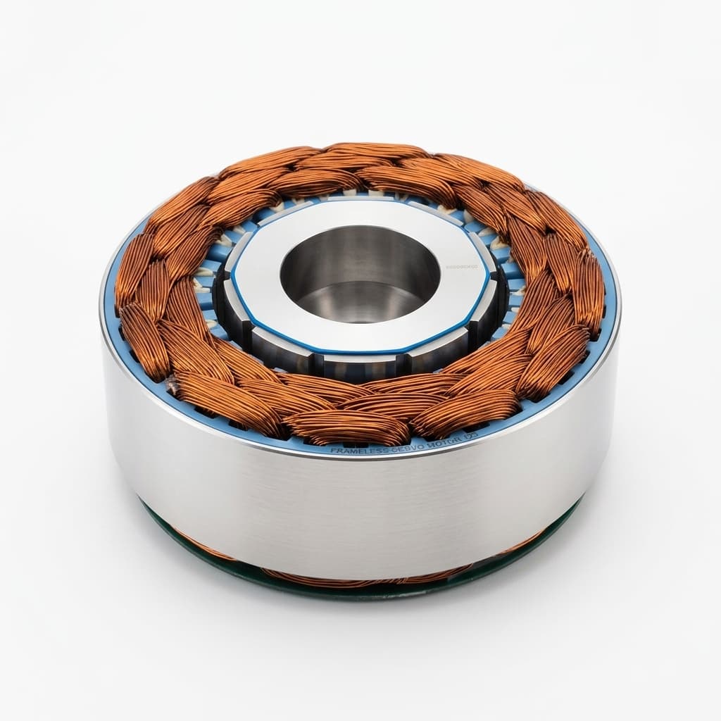
Frameless Servo Motor Thermal Sensor Selection & Placement: PT1000 vs. NTC vs. PTC in High-Density Joint Actuators
Specify frameless servo motor thermal sensors: compare PT1000, NTC, PTC, end-turn placement, thermal time constants, and RFQ dielectric insulation requirements.
Frameless servo motor thermal protection depends on sensor compatibility, placement, and coordinated drive limits. A frameless stator/rotor kit leaves the OEM responsible for validating the final housing's cooling path, sensor response, and fault behavior. A housing-mounted sensor may substantially lag the winding during overload; the actual delay depends on construction and operating conditions. Winding temperature also does not directly establish rotor magnet temperature.
For high-torque-density robotic joints, compact hollow-shaft actuators, and automated guided vehicles (AGVs), start with this selection rule: use PT1000 for continuous temperature feedback when the drive supports it; use NTC when its exact curve and input circuit are qualified; use a PTC triplet for threshold monitoring across phases. An independent trip channel can supplement continuous feedback, but its need and safety role depend on the machine risk assessment.
Published and reviewed: 2026-11-11. Scope: Global OEM motion control engineering, robotics joint design, and electrical procurement teams integrating inner-rotor, permanent-magnet synchronous frameless motors (PMSM/BLDC). This guide provides sensor selection criteria, placement checks, and a procurement acceptance checklist. Calculations are illustrative, not measured motor performance, product specifications, or certification evidence. Validate each design against the selected sensor, motor, drive, and final actuator assembly.
For active robotic joint programs, request an engineering winding and thermal sensor review with your motor frame dimensions, peak/continuous current profiles, ambient thermal limits, and target servo drive architecture.
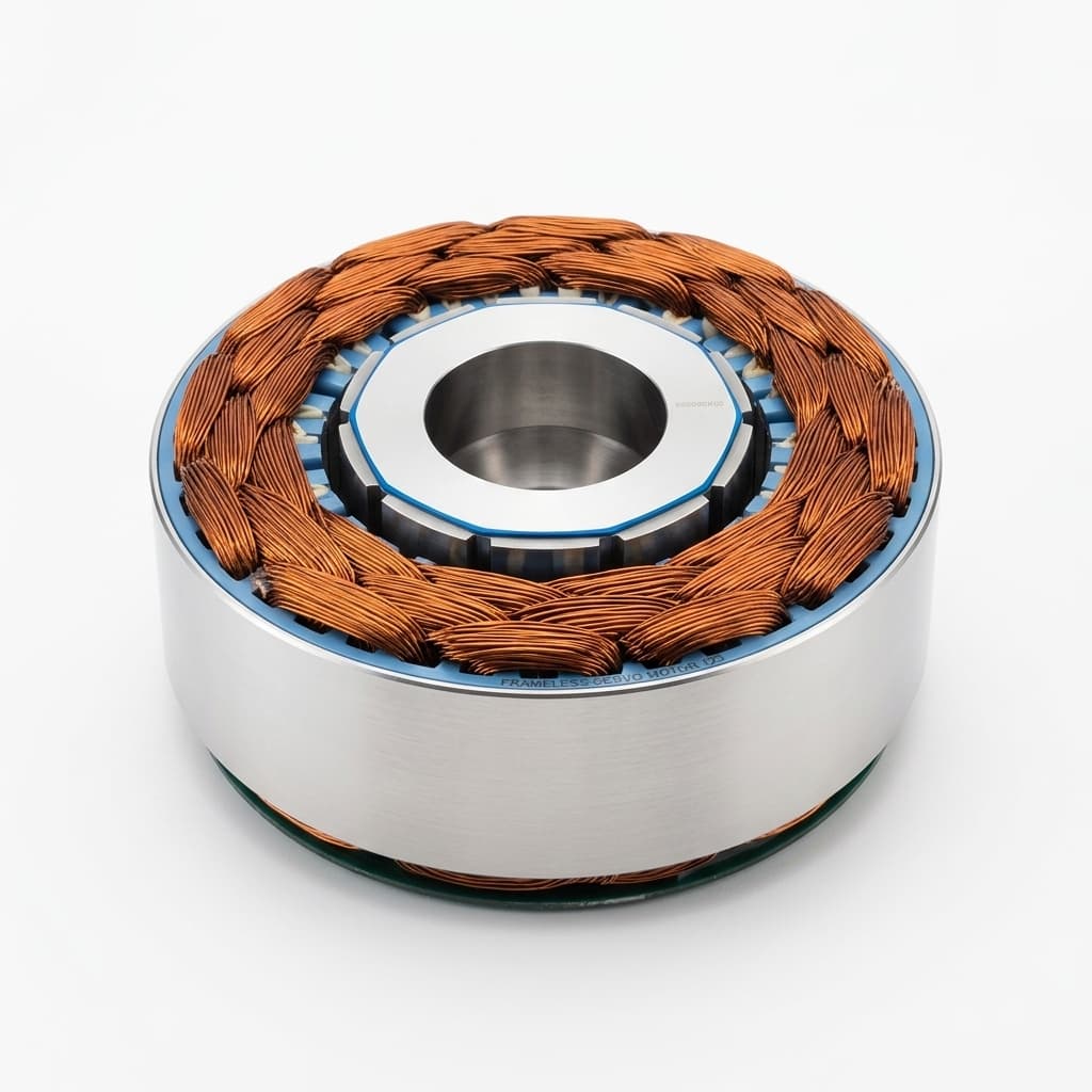
Stator illustration showing copper end-turns. The image does not show an installed sensor or establish the thermal hotspot; confirm both on the supplier drawing and assembled-motor test.
1. The Core Engineering Trade-Off: Sensor Physics & Operating Curves
Selecting a temperature sensor for an embedded frameless stator is not simply a line-item bill of materials (BOM) choice. It dictates how the motion controller handles thermal limits: whether it performs graceful closed-loop current throttling (derating torque output as thermal margins diminish) or relies on an abrupt binary trip that cuts power to an active robotic axis.
1.1 PT1000 RTD (IEC 60751): Continuous Servo Telemetry
A PT1000 has a nominal resistance of 1,000 Ω at 0°C. Its platinum curve makes temperature conversion reproducible across conforming parts. Texas Instruments' RTD measurement guide, sections 1.1–1.3, explains the curve, tolerance classes, and lead compensation.
For positive temperatures, use the Callendar–Van Dusen form R(T) = R0 × (1 + A × T + B × T²). Here T is in °C, A = 0.0039083, and B = −0.0000005775. This gives approximately 1,385.1 Ω at 100°C. The relationship is near-linear over a limited range, but conversion should use the specified curve rather than a fixed slope. Sub-zero operation needs the additional negative-temperature term.
Why PT1000 rather than PT100? A calculated lead-resistance comparison helps: at approximately 3.85 Ω/°C, a PT1000 with 2 Ω total series lead resistance has about 0.52°C offset. A PT100 at approximately 0.385 Ω/°C has about 5.2°C offset. These are local approximations, not complete accuracy budgets. Include sensor tolerance, connector changes, excitation self-heating, and input error. PT100 remains viable with a suitable compensated interface.
Before selecting a sensor, confirm the drive's exact input type, excitation limits, wiring, and firmware support. A resistance input labeled “motor temperature” does not necessarily accept every RTD or thermistor.
1.2 NTC Thermistors: Match the Curve and Input Circuit
Negative Temperature Coefficient (NTC) thermistors offer compact packaging and economical continuous feedback. A label such as “10 kΩ NTC” is incomplete: it identifies resistance at a reference temperature but does not fully specify the curve, tolerance, or maximum operating temperature.
For an illustrative 10 kΩ-at-25°C device with a constant beta of 3,950 K, calculate R(T) = 10000 × exp[3950 × (1/T − 1/298.15)], with T in kelvin. The result is approximately 698 Ω at 100°C, 318 Ω at 130°C, and 179 Ω at 155°C. This simplified beta model demonstrates the trend; use the selected part's table or coefficients for production conversion.
Resistance sensitivity falls at high temperature, but usable temperature resolution depends on excitation, divider resistance, ADC range, filtering, and calibration. NTC is therefore a valid choice when the entire channel meets the required error budget. Do not assign a universal high-temperature error to all NTC interfaces. Freeze both resistance tolerance and curve tolerance in the purchase specification; an unapproved substitute can shift reported temperature even if its room-temperature resistance matches.
1.3 PTC Thermistor Triplet: Threshold Monitoring
Motor-protection PTCs increase resistance sharply around a specified nominal response temperature. They are useful for detecting an overtemperature threshold rather than reporting a calibrated winding temperature. TDK's application notes, section 1.5.2, describe winding contact and series-connected sensors for monitoring multiple phases.
The PTC chain connects to a compatible evaluation input, not to the motor power conductors. Select the chain length, response temperature, evaluator trip/reset levels, and wire-fault diagnostics together. Open circuits may resemble an overtemperature condition; a short can conceal heating unless the evaluator detects it.
A PTC signal does not automatically provide Safe Torque Off (STO), a safety-rated shutdown, or an instantaneous response. Those properties belong to the complete protection circuit and its validation. Continuous feedback can also be combined with a current-based thermal model; a PTC trip channel does not replace fast current limiting.
1.4 Legacy KTY84-130: Treat Replacement as an Engineering Change
Legacy drawings may specify KTY84 silicon sensors. Their resistance–temperature curve differs from PT1000; sharing a nominal resistance value at different reference temperatures does not make them interchangeable. Confirm lifecycle, authorized availability, and the exact original part before procurement. If migrating to PT1000, update the motor drawing, drive conversion, and warning/trip settings together. Verify indicated temperature at multiple controlled points before operation. A universal parameter number or fixed temperature offset cannot safely describe that migration across drives.
2. Sensor Technology Benchmark Matrix
Use this matrix to screen interfaces before requesting a stator quotation. Packaging, insulation, and assembled response still require separate qualification. Relative BOM descriptions are qualitative, not supplier price quotations.
| Sensor / configuration | Main role | Drive interface requirement | Principal trade-off | Procurement evidence | Selection boundary |
|---|---|---|---|---|---|
| PT1000, 2-wire | Continuous feedback | Matching platinum curve | Lead resistance adds offset | Part, class, harness resistance | Good candidate when total error is acceptable |
| PT1000, 3/4-wire | Continuous feedback | Compensated RTD input | More conductors and terminals | Wiring diagram and channel accuracy | Use when the input supports compensation |
| PT100, 3/4-wire | Continuous feedback | PT100-compatible input | Greater sensitivity to uncompensated lead resistance | Compensation and connector details | Valid with a qualified measurement chain |
| NTC, e.g. 10 kΩ | Continuous feedback | Exact curve or lookup table | Curve and input design govern accuracy | R25, curve, tolerances, temperature rating | Economical when the full channel is qualified |
| Motor-protection PTC triplet | Threshold monitoring | Compatible trip evaluator | No calibrated continuous temperature output | Response temperature, chain limits, fault behavior | Consider for phase coverage or a separate trip channel |
| Legacy KTY84 | Existing-system feedback | Matching silicon-sensor profile | Substitution and lifecycle risk | Exact part identity and availability | Retain or migrate through change control |
| Type K thermocouple | Development measurements | Thermocouple input with cold-junction compensation | Small signal and installation sensitivity | Isolation and reference-junction method | Useful for testing with suitable acquisition hardware |
No sensor family inherently guarantees PWM noise immunity. That depends on cable routing, insulation, filtering, grounding, and input design. Digital sensors are also possible in purpose-designed assemblies, but bus compatibility and environmental qualification must be demonstrated.
3. Physical Placement & Thermal Time Constant Modeling
Sensor placement determines which part of the motor is observed. A steady-state temperature reading alone does not show whether that sensor follows the fastest relevant winding transient. Evaluate both spatial temperature difference and time delay in the final actuator housing.
A simplified sensor-response model is Ts(t) = Ts(0) + [Tw − Ts(0)] × (1 − exp(−t/τs)) after an ideal step in local winding temperature Tw. The sensor reaches about 63% of that step after one time constant τs. This is a screening model, not a prediction of a motor whose heat input and winding temperature are changing simultaneously. Do not confuse sensor lag with the motor assembly's heating time constant.
3.1 Zone A: Copper End-Turn Embedding
An insulated sensor in close thermal contact with an end-turn bundle can track local copper temperature more directly than a remote housing sensor. Confirm the hotspot location rather than assuming the lead-out side or Phase U is always hottest. End-turn exposure, slot cooling, potting, and winding topology can change the temperature distribution.
The manufacturing drawing should define sensor position, dielectric barrier, bonding or lacing method, lead strain relief, and inspection before impregnation. Thermal contact must preserve electrical insulation; never require a bare element to touch a live conductor. Potting voids, excess adhesive thickness, and replacement sleeving can alter response without changing the sensor part number.
3.2 Zone B: Slot Center / Tooth Gap
A slot-mounted sensor may be closer to a hotspot in some cooling arrangements, but installation must preserve slot liners and conductor insulation. Ask how the element fits the winding process and how its position is verified after assembly. A sensor in a tooth gap measures a different thermal path from one embedded within a copper bundle; the drawing should distinguish them.
3.3 Zone C & Zone D: Stator Yoke and Housing Flange
Yoke and housing sensors are useful for cooling-system monitoring and steady-state correlation. They may read substantially below the winding temperature during a short overload. There is no universal 30–90-second delay or fixed winding-to-housing temperature offset. Measure the installed assembly rather than copying a response time from a bare sensor datasheet. A housing sensor alone should not be assumed to protect a winding against a rapid stall.
3.4 A Reproducible Placement Qualification Procedure
Use a controlled development test, with independent current and temperature limits, to compare candidate locations:
- Freeze the boundary conditions. Record stator variant, winding, potting, housing fit, cooling, ambient, bus voltage, and the actual duty cycle.
- Establish a reference. Use calibrated, appropriately isolated instrumentation near candidate hotspots. A thermocouple, fiber-optic probe, or winding-resistance estimate has different spatial and timing limits; record the method.
- Capture the whole channel. Log reference temperature, installed sensor output, phase current, drive temperature indication, and cooling state on a common timebase. State sample interval and input filtering.
- Exercise credible loads. Include representative continuous operation and approved short overloads. Test different held rotor positions where stationary phase heating may vary; do not exceed supplier limits to demonstrate a fault.
- Set margins from evidence. Record maximum under-reading and total delay, including filtering and stop action. Repeat after relevant process changes and retain traceable sample identifiers.
For an arithmetic example only, assume a 150°C winding limit, a measured worst-case under-reading of 10 K, an additional 3 K uncertainty allowance, and 5 K further heating before the stop completes. The indicated stop threshold would need to be no higher than 150 − 10 − 3 − 5 = 132°C under those assumptions. This is a margin calculation, not a recommended setting or a measured result for our motors. If the margin cannot be demonstrated, improve placement, reduce allowable current, or revise the cooling design.
4. Dielectric Insulation & Inverter dV/dt Noise Isolation
PWM switching can couple common-mode transients into sensor leads near phase conductors. The actual stress depends on bus voltage, switching edges, cable length, and grounding. A low nominal DC bus does not by itself establish touch safety or sensor-input immunity.
4.1 Define the Insulation Boundary Before the Test Voltage
Use the motor and drive documentation to determine required separation between the winding, sensor circuit, accessible parts, and control electronics. IEC 60664-1 and IEC 61800-5-1 may be relevant to insulation coordination and drive safety, but their application requires the actual equipment classification and installation conditions. This guide does not establish compliance with either standard.
Ask the supplier to identify working voltage, transient stress, insulation category, temperature rating, and the applicable qualification method. Specify the approved dielectric test voltage, AC/DC waveform, duration, leakage criterion, and which terminals are connected together. Distinguish a type test from a production routine test. Do not copy a universal 500 V or 2,500 V test into every RFQ; an unsuitable test can damage the assembly or provide misleading assurance.
Disconnect sensitive electronics as required by the test procedure. A sleeve material name alone does not establish insulation adequacy: wall thickness, seams, abrasion, chemical compatibility, aging, and the installed construction all matter.
4.2 Common-Mode Noise and Measurement Filtering
The displacement-current relationship is i = C × dV/dt. As an illustrative edge calculation, 30 pF exposed to 15 kV/µs gives 0.45 A. That is a brief coupling-current estimate, not a continuous current or a prediction of current entering the ADC. The actual path depends on impedance, shielding, and protection components.
Route sensor pairs away from phase wiring where practical, minimize loop area, and follow the drive manufacturer's shield and grounding instructions. Polyimide barrier tape is insulation, not a conductive shield. Avoid prescribing one shield termination arrangement for every installation.
Filtering must suit the input's excitation and diagnostic circuits. For a simple RC stage, fc = 1/(2πRC) is a starting calculation; a differential interface may require a different equivalent circuit. Include analog and digital filter delay in the protection budget. Filtering can reduce differential noise but does not replace common-mode protection or insulation. Verify temperature stability and fault detection under the installed inverter's worst relevant switching and load conditions.
5. A Hybrid Architecture for Robotics Joints
A continuous sensor plus a separate threshold channel can improve coverage when the drive supports both. This is a candidate architecture, not a universal requirement or a claim of safety certification.
THERMAL CONTACT with windings; sensors are electrically insulated

Local winding sensor: PT1000 or matched NTC
    -> compatible temperature input -> warning / current derating

PTC at U -- PTC at V -- PTC at W (sensor-only series circuit)
    -> compatible evaluator -> configured drive stop / fault response
The two channels need compatible electrical interfaces. Do not parallel unlike sensors onto one temperature input or connect a sensor chain to U/V/W power terminals. Review common failure causes such as a shared connector, damaged harness, or loss of evaluator power before calling channels independent.
Choose warning, derating, and stop thresholds from the lowest relevant motor-system limit and the measured margins described above. A fixed percentage current reduction cannot be prescribed without the duty cycle and motion behavior. Derating can affect trajectory tracking and gravity compensation; a controlled stop may require coordinated brakes and load support.
An ordinary PTC evaluator output does not become an STO function merely because it triggers a drive fault. If the application requires a safety-rated reaction, select the appropriate evaluated architecture and verify its diagnostics and stopping behavior separately. Fast electrical faults and short overloads still need drive current protection even when both thermal channels are present.
Before freezing the stator design, request a sensor and drive compatibility review with the exact input specification, proposed placement drawing, and required stop behavior. This gives procurement a concrete configuration to quote and validate.
6. Engineering & Procurement Acceptance Checklist
Before approving a frameless servo motor drawing revision or releasing a production purchase order, verify that the supplier's specification sheet and factory quality plan address these eight deliverables:
- 1. Sensor specification and curve: Record exact part number, resistance reference point, tolerance, usable temperature range, and conversion curve. Reject ambiguous designations such as “standard 1k thermistor.” Control substitutions through engineering approval.
- 2. Physical placement: Require a marked drawing with phase coverage, axial location, insulation barrier, and assembly method. Record why the location represents the relevant hotspot; request inspection evidence before potting.
- 3. Insulation and dielectric testing: Agree the approved separation requirement and test procedure, including voltage, duration, leakage limit, terminal grouping, and electronics disconnection. Require a traceable test record rather than a generic “hipot passed” statement.
- 4. Lead wire and strain relief: Specify insulation temperature, voltage, flex life, bend radius, chemical compatibility, and strain relief for the actual joint motion. The wire rating must suit both the winding environment and moving harness.
- 5. Identification and connectors: Put T1/T2 or other unambiguous sensor pin names on the released drawing. Use a connector/pinout distinct from phase power and feedback signals; color coding alone is insufficient.
- 6. Inverter compatibility: Agree cable routing, shielding, grounding, and input-filter settings. Check temperature indication and diagnostics during representative PWM operation and electrical transients.
- 7. Factory acceptance data: Record baseline resistance alongside measured reference temperature and instrument uncertainty. For example, the nominal PT1000 calculation gives about 1,097.3 Ω at 25°C; ambient variation and total channel error must be included in the acceptance band. A room-temperature reading does not prove response at the trip point.
- 8. Drive alignment and fault response: Record drive model, firmware, sensor setting, thresholds, current limits, reset behavior, and test results for open/short sensor wiring. Include assembled transient qualification and any separate PTC evaluator details in the approval pack.
For supplier comparison, ask every bidder to return the same evidence fields. Separate missing evidence from a failed test: an unspecified curve or location remains an open qualification item, even if the quoted price and sample lead time are attractive. Requalification should follow changes to sensor, potting, harness, placement, drive firmware, or cooling boundary.
7. Frequently Asked Questions (FAQ)
Q1: Can I use a PT100 sensor instead of a PT1000 in my frameless servo actuator?
Yes, when the drive has a matching PT100 input and the complete measurement chain meets the required accuracy. PT100 is more sensitive to uncompensated series lead resistance, so suitable three- or four-wire measurement may be valuable. A PT1000 reduces this particular error but does not automatically make a two-wire installation accurate enough.
Q2: Why did my motor overheat even though the sensor stayed below 110°C?
Possible causes include sensor lag, an unmonitored hotspot, an incorrect conversion curve, wiring faults, inadequate current limits, or an incorrect allowable temperature. Compare the installed reading with independent winding measurements and inspect the configured fault response. One low sensor reading cannot identify the root cause or establish that the rotor magnets remained within their limit.
Q3: How do I protect the sensor from GaN/SiC drive PWM noise?
Validate insulation and common-mode limits, route the signal pair carefully, and use shielding and filtering appropriate to the selected drive. Check both stable temperature readings and detection of wire faults while the inverter operates. A smooth filtered reading alone does not prove immunity; excess delay can hide a relevant transient.
Q4: Can a single thermal sensor protect all three motor phases?
It may provide sufficient feedback for a validated operating envelope, but a single local reading cannot guarantee coverage of every phase imbalance or stationary holding condition. Map relevant hotspots and determine whether additional sensors or a PTC triplet are required. Additional devices need appropriate placement and evaluation; their count alone does not establish redundancy or functional safety.
Q5: What is the difference between a PTC thermistor and a bimetallic thermal switch?
A motor-protection PTC changes resistance and needs a compatible evaluator. A bimetallic switch changes a mechanical contact state and must match the receiving circuit's electrical ratings. Compare installed response, tolerance, hysteresis, packaging, and environmental qualification. Neither technology has universal vibration immunity or a guaranteed sub-second installed response.
Q6: What should I do if my legacy design uses KTY84-130?
Confirm the original sensor identity, availability, and drive configuration. Treat migration as an engineering change affecting hardware, conversion, and thresholds. Check multiple controlled temperatures and sensor-fault behavior before releasing the replacement. Do not use a parameter value copied from a different drive generation or assume the two curves differ by a constant offset.
8. Sources & Technical References
References checked on 2026-11-11 using accessible document text and publisher search records. These sources support sensor/interface principles; the calculations and qualification workflow above are explicitly illustrative. No unpublished test results or universal drive parameter mappings are claimed. Standards applicability and production settings require the project's approved documentation.
- Texas Instruments: A Basic Guide to RTD Measurements, SBAA275A, revised March 2023 — Sections 1.1–1.3 explain platinum RTD conversion, tolerances, and wiring effects. This is an input-design reference, not motor qualification evidence.
- TDK Electronics: PTC Thermistors: Application Notes — Section 1.5.2 describes direct winding contact, series-connected phase monitoring, and compatible tripping units. It does not establish a safety rating for an OEM circuit.
- Siemens: SIMOTICS 1FW6 Built-in Torque Motors: Configuration Manual, September 2022 — Section 5.1, including Table 5-2, illustrates model-specific PTC characteristics. Those response temperatures and resistance limits must not be copied as specifications for another motor. Publisher-host access may require a browser/session.
Request a Custom Thermal Sensor & Winding Engineering Review
Avoid thermal bottlenecks, unexpected stall burnouts, and inverter noise tripping before finalizing your robotic joint housing or stator tooling. Submit your motion profile, peak torque requirements, target drive model, and mechanical boundary drawings to our engineering team.
Explore our high-performance direct-drive product platforms:
- Frameless Servo Motor Kits — Stator/rotor platforms for discussing winding, sensor, and housing integration requirements.
- Hollow Shaft Frameless Servo Series — Large clear-aperture direct-drive motors engineered for integrated cable and optics routing.
- Torque Motor Series — Direct-drive platforms for reviewing torque, cooling, and thermal acceptance requirements.
Connect directly with our applications engineering team through our Contact & RFQ Consultation portal to discuss sensor configurations, custom encapsulation, and sample lead times.
Author

More Posts
Frameless Servo Motor Winding Customization: Optimizing KV Rating and Phase Resistance
Learn when to request frameless servo motor winding customization, how KV rating changes phase resistance, and what to send suppliers for RFQ review.
Frameless Servo Motor Compliance & EU Machinery Regulation (EU) 2023/1230: CE Boundaries, LVD, UL, and OEM Procurement Documentation
Navigate frameless servo motor compliance for 2027: EU Machinery Regulation (EU) 2023/1230 boundaries, 48V vs. 400V LVD scope, UL 1004-1, RoHS, and PFAS readiness.
Frameless Servo Motor Commutation Alignment: Establishing Electrical Zero in High-Performance Joint Actuators
Frameless servo motor commutation alignment: compare electrical-zero methods, avoid encoder errors, and prepare an RFQ checklist for your integration review.